Unique Question Concerning Injection Timing

cut7

New member
Joined
Dec 27, 2012
Messages
124
Perhaps a bit of background is in order. I am fitting a Bosch H-1000 injection pump to my 12v motor. The H-Pump has dynamically variable timing (a total of 14.8° of pump advance, or 29.6° of crank advance; the pump spins at 1/2 crank speed).

What I am trying to do is figure out a general advance curve (RPM vs. Degrees of advance) and also a 3-D curve which would include throttle position and possibly MAP, or MAF. I downloaded the demo version of EFI Live and looked at a few curves that are in the library, but what I can't figure out is: Is there a static number degrees of initial timing, and the computer advances or retards from there. Or is the initial timing a very low number, perhaps even ATDC and then advances from that point. I am not concerned about emissions, so like I said I am just looking for a basic 2D curve and then modify it for additional advance under light throttle, light boost conditions. I'm convinced the ability to advance timing is the reason common rail motors can get higher power numbers & still remain streetable.

Also, something to consider, pilot injection is not possible with this pump, so total timing in degrees BTDC, not just advance from a certain point, is what I'm looking for.

I'm posting here because the P-Pump guys don't know much about dynamic timing because it doesn't apply to them; since the P-Pump can't dynamically advance.

Any positive input is appreciated. If further clarification of my project is needed, please don't hesitate to ask.
 
Last edited:
What rpm range are you looking to cover, and being that I'm not familiar with this pump, what mechanism does the timing advance? Is the timing advance linear to RPM, or does it happen all at once?
 
Thanks for your reply!

RPM range is idle to 4k max. This is a compound turbo street truck which will never be entered into competitions. The H-pump is similar to a P-pump except that it has an additional rack to advance timing, & the pressure rise is much faster, & the peak pressure is much higher (approaching CR pressures). The fueling & timing racks are electrically actuated; & are totally independent of each other. Just like a P-pump, you statically set the pump — to say, 10°, or whatever you desire as a starting point — then the advance rack will advance timing from there. So if I started at 10° initial timing (measured at the crank) I could program a curve with a maximum of 39.6°. To reiterate, the timing rack has nothing to do with the position of the fueling rack, they are totally separate functions. In other words, I can program in whatever curve I want, within the parameters of the total advance available by the rack (which is 29.6°). With the pump initially timed at a modest 10°, it is theoretically possible to get 39.6° advance at idle (though I don't know why anyone would want to do that!) :doh:

Does that answer your question? Or should I elaborate further?

Once again, thanks for your comment. I'm hoping this will be an intelligent & informative thread for all.
 
Last edited:
Sounds like a fairly good idea especially if you can control it across the RPM range. I think one would want to start somewhere around 6-8* and advance from there. At 4000 rpm ending up in the 34-36* range would work. How is the rack controlled?
 
How is the rack controlled?

Simply apply voltage to it, anywhere from 0-12v. The injection advance vs. voltage applied is pretty linear; I have a spreadsheet detailing the movement in 1° steps.


Sounds like a fairly good idea especially if you can control it across the RPM range. I think one would want to start somewhere around 6-8* and advance from there. At 4000 rpm ending up in the 34-36* range would work.
I was thinking along similar lines — 10° at idle to about 32° at 3200 rpm.

What about additional advance during light throttle, medium rpm (cruise) conditions? How much supplementary advance to maximize mileage?
 
Last edited:
Dependent of RPM and MM3, speaking common rail, on a single event tune I'm ussually 10-14 degrees in the area where you cruise.
 
Dependent of RPM and MM3, speaking common rail, on a single event tune I'm ussually 10-14 degrees in the area where you cruise.

Is that 10°-14° additional advance? Meaning on top of the advance due to RPM? e.g. If I'm cruising at 1800 RPM & I have 18° of advance, then I add 10°-14° more on top of the 18°?

What I'm talking about here is a 3-D curve; the advance vs. RPM being a 2-D curve.
 
Last edited:
BTW, I know how many CCs of fuel I'm injecting at any given rack position; so general common-rail speak roughly applies here.
 
If your goal was 18* btdc at 1800 and you had the pump set at 10* btdc then your just wanting to add 8* advance.
 
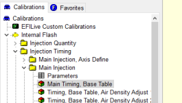
So with EFILive the main timing tables are pretty much what you see is what you get and they are referenced to TDC. Now it will add timing when coolant or intake temps are low. It will also change timing tables or blend between two with changes to barometric pressure. For the most part the main timings follows the base table on a 5.9.

One thing I was wondering is what is moving the rack? Is it a coil? I design controllers for proportional hydraulic valve and when the coil heats up the resistance increases thus reducing current and flow, so for them we use constant current drivers which solves this. I thought it might be worth mentioning if this thing uses a coil.


Sent from my SM-G935V using Tapatalk
 
Thanks for your reply.

Where would I find this base table you refer to?

You make a really excellent point about resistance changing with heat. The pump has a rack position sensor which allows the controller to see where the rack is ,as opposed to where it thinks it ought to be, & adjust accordingly.
 
Last edited:
Capture.PNG
so the base timing table is the one i have highlighted.
also the stock 5.9 timing wouldn't run a single injection tune, i think about a min of 5 deg is whats required to run on my truck with a warm engine.

cool project btw!
 
1degree/100rpm is a good rule of thumb to start with. That is at max load, part load you want less advance. BTW, it is 0-5 volts, not 12 volts.
 
where is the feed for the timing coming from based on rpm? or is it a set programmed map that isn't dynamic...which is good on a race setup from base to wide open but not so much on constantly changing rpms on a street driver?

reading a crank sensor or something?
 
I personally think you're dead on with starting at 10deg advance.

The lowest a stock 12V had was 12deg I believe, and that was obviously a compromise so it still had some power all the way up to it's 2600rom red line.

I'd probably start at 10deg idle, and do a linear timing progression to 32deg at 4000rpm. Then start tweaking it.

You also have to figure out, or keep in mind, that your injection event is likely different than the p7100 pump, and is definitely different than the common rails.
A lot of the advance timing on 12mm pumps at higher rpms is to make up for the slow injection event. If you had the data to show the middle of the injection even on a 12mm p7100 pump at 4000rpm, I bet it'd be a good 5-10deg retarded than where you set it. Does that make sense? It's definitely a little wordy
 
1degree/100rpm is a good rule of thumb to start with. That is at max load, part load you want less advance. BTW, it is 0-5 volts, not 12 volts.

I have done substantial test on this pump, it's 0-12v to operate both the timing & fueling racks; the fueling rack has a feedback circuit which is 0-5v.
 
I personally think you're dead on with starting at 10deg advance.

The lowest a stock 12V had was 12deg I believe, and that was obviously a compromise so it still had some power all the way up to it's 2600rom red line.

I'd probably start at 10deg idle, and do a linear timing progression to 32deg at 4000rpm. Then start tweaking it.

You also have to figure out, or keep in mind, that your injection event is likely different than the p7100 pump, and is definitely different than the common rails.
A lot of the advance timing on 12mm pumps at higher rpms is to make up for the slow injection event. If you had the data to show the middle of the injection even on a 12mm p7100 pump at 4000rpm, I bet it'd be a good 5-10deg retarded than where you set it. Does that make sense? It's definitely a little wordy
Yes it makes sense. I see what you're saying, but I'm not sure I agree with you. Having said that, it's always good to consider dissenting opinions; especially from a fellow mechanical engineer. I guess a good place to start would be find out what max timing is on a performance common rail tune that does not make use of pilot injection. Anybody want to contribute that info?

BTW, the curve you've suggested is exactly what I plan to do. (Great minds think alike!) ;)
 
Last edited:
where is the feed for the timing coming from based on rpm? or is it a set programmed map that isn't dynamic...which is good on a race setup from base to wide open but not so much on constantly changing rpms on a street driver?

reading a crank sensor or something?

I am reading the RPM — & other several factors — from the CAN bus; which is getting it's RPM data from a 60-2 reluctor wheel on the damper, read by a 0-5v Hall-effect sensor. From there, my controller commands the timing & fueling racks; the timing based on a table. It also controls the waste gate of my compound turbos; but that's not relevant to this conversation.
 
Last edited:
Back
Top