jlibert
New member
I've seen several threads asking for help with twin turbo installation. Here are the installation instructions for Source Automotive's kit on a 2004.5 NV5600 4x4. Hope this helps.
-jp
Source Automotive Twin Turbo Installation Procedure, 2003-2007 Dodge, 5.9 Cummins Engine.
1. Open packages to verify that you have received all of the necessary parts.
2. Disconnect battery cables from both batteries, remove keys from ignition. Set parking brake. Failure to take these steps can result in serious injury or death!
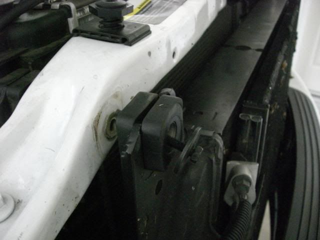
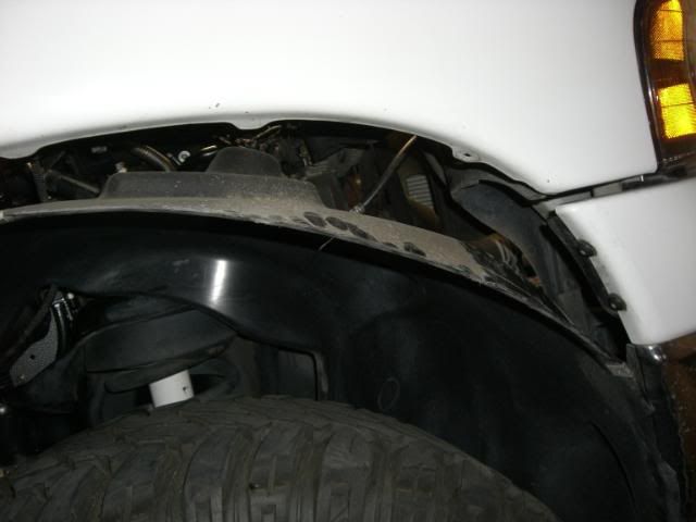
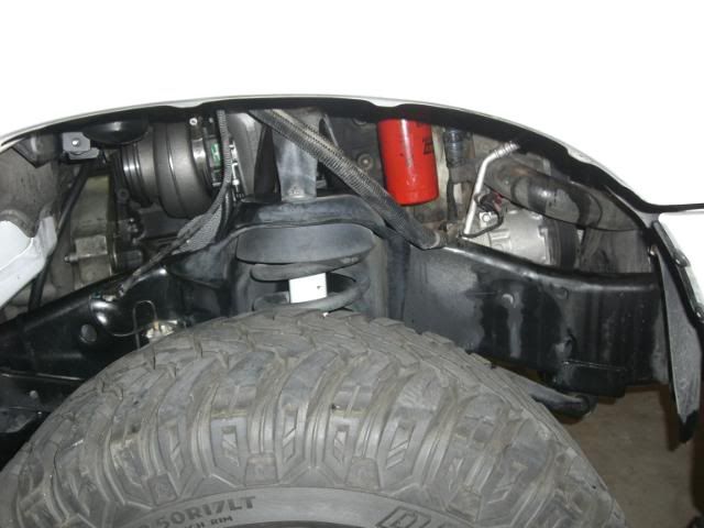
3. Remove plastic inner fender as shown below. Several 8mm bolts hold it in place. There may be one or more plastic tabs used to hold wiring that will need to be detached from inner fender before it can be fully removed.
4. Remove existing turbocharger and exhaust manifold:
a. Disconnect and remove existing downpipe.
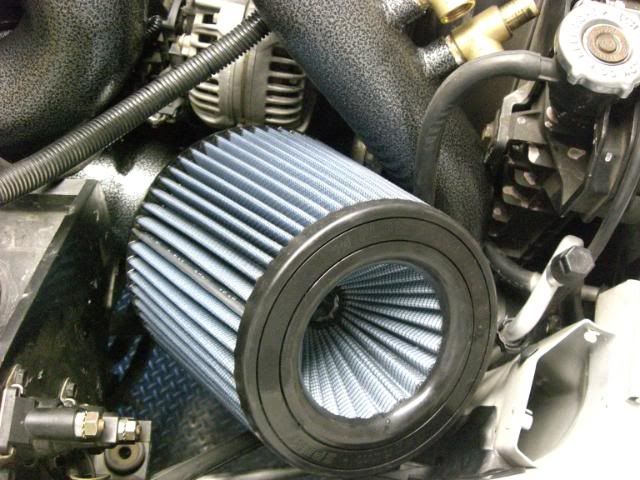
b. Remove existing intake/filter assembly.
c. By laying under the truck, firmly grip the turbo oil drain line and pull it out of the block. A bit of force may be required to pop the drain line out of the hole in the block.
d. Remove the braided steel oil supply line that runs to the top of the turbo.
e. Remove all bolts from exhaust manifold and pull turbo and manifold out in one piece. (help from another person may be necessary when lifting manifold/turbo out of engine bay)
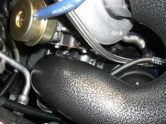
Your engine should look something like this at this point:
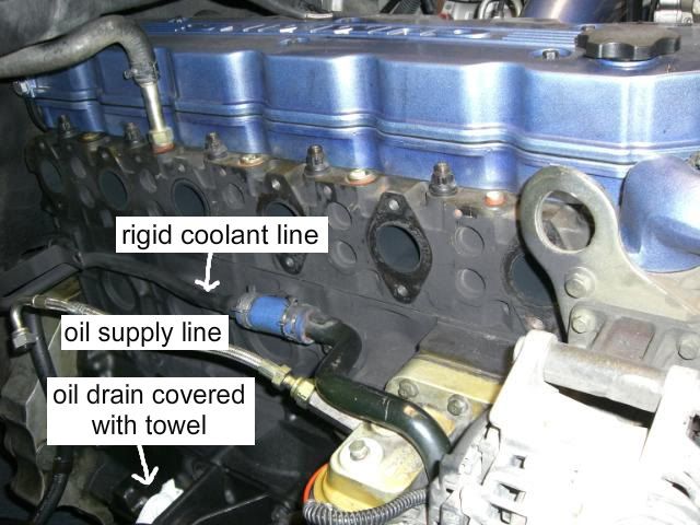
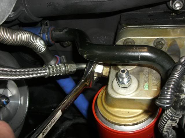
5. Remove rigid coolant line from blue silicone hose to firewall shown in picture above. A bucket should be placed below the line to contain coolant lost when line is removed.
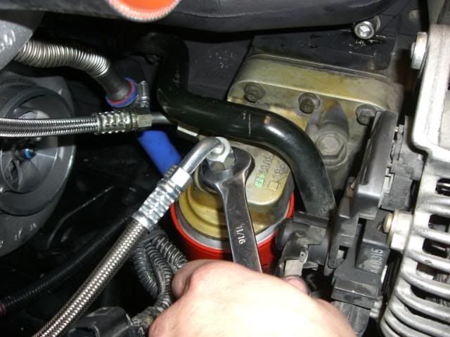
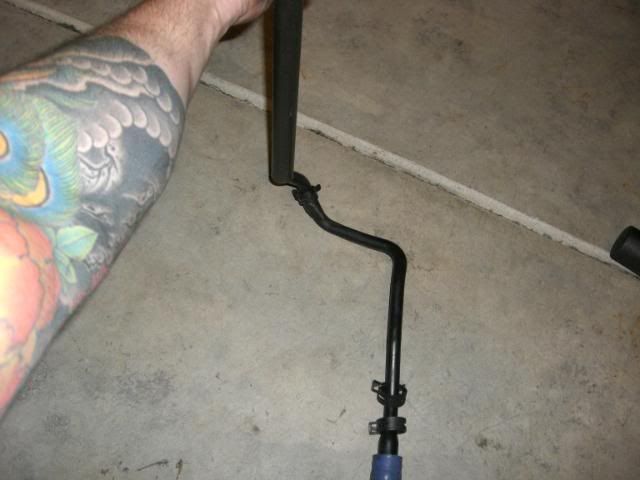
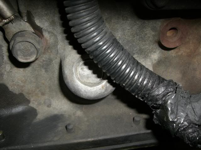
6. Using a piece of pipe and a rubber mallet, reshape the rigid line as shown in the following images:
Tap rigid hose with rubber mallet to slightly flatten the factory bend.
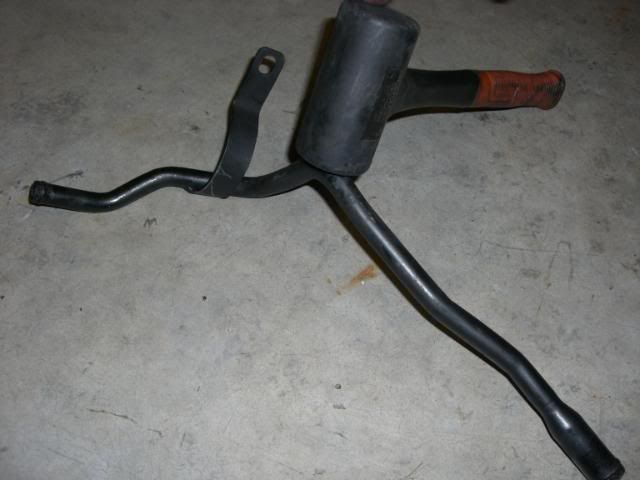
Slide a piece of pipe over the end of the rigid line as shown below, using the pipe to bend the rigid line into a shape that will clear the top turbo. After turbo is installed, additional adjustments may be needed. This took a first time installer less than 5 minutes to complete, it isn’t hard.
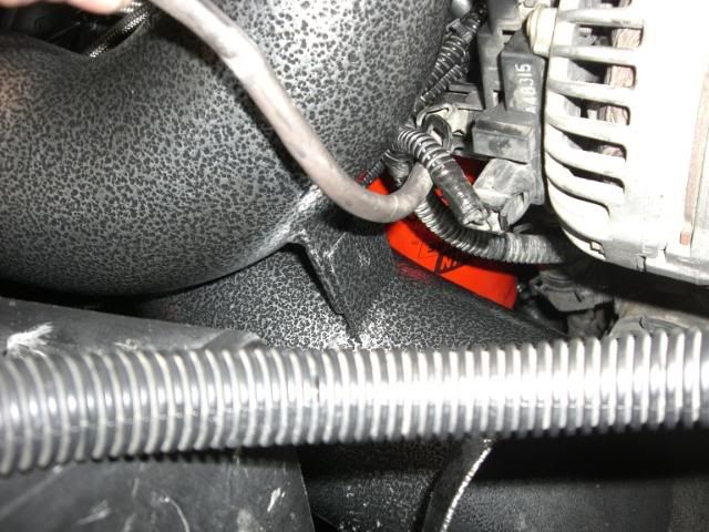
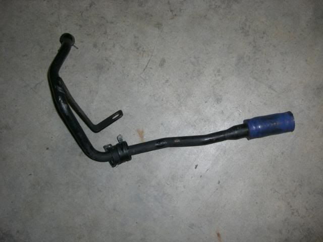
rigid coolant line before bending:
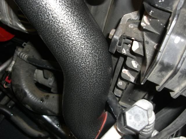
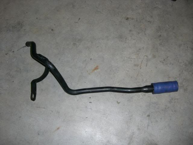
rigid coolant line after bending:
7. If you choose to paint your exhaust manifold, VHT flameproof paint works great.
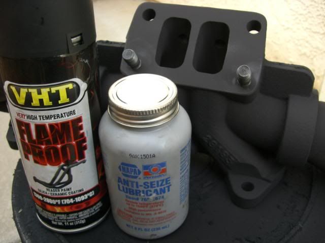
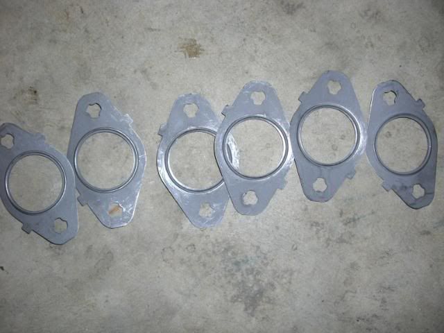
Install the longer studs included from source automotive into the manifold. (the shorter studs supplied with the manifold will not be used) Apply never seize to studs. Install steel spacer and gaskets as shown below:
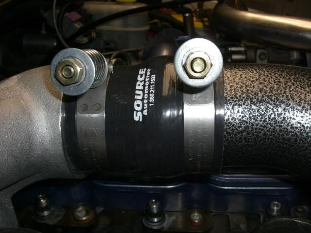
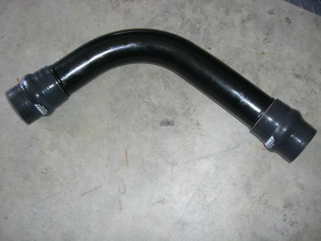
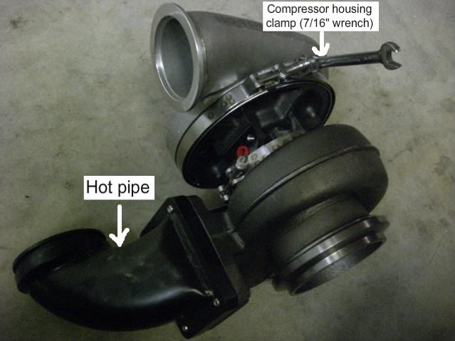
8. Loosen the compressor and exhaust housing clamps on the primary (big turbo) just enough so that the housings can be rotated as needed later in the install. Attach the hot pipe to primary turbo as below.
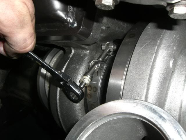
9. Remove secondary turbo (small turbo) compressor and exhaust housing bolts one at a time as shown below. Install never seize to threads and reinstall bolts loosely. This will allow the housings to be rotated to achieve proper alignment later in the install.
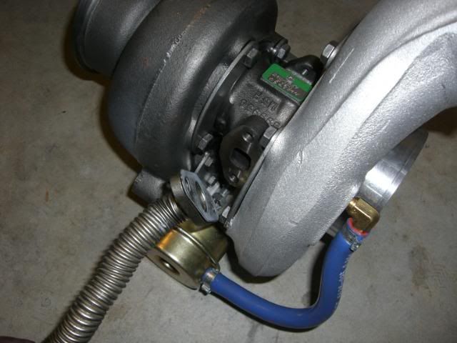
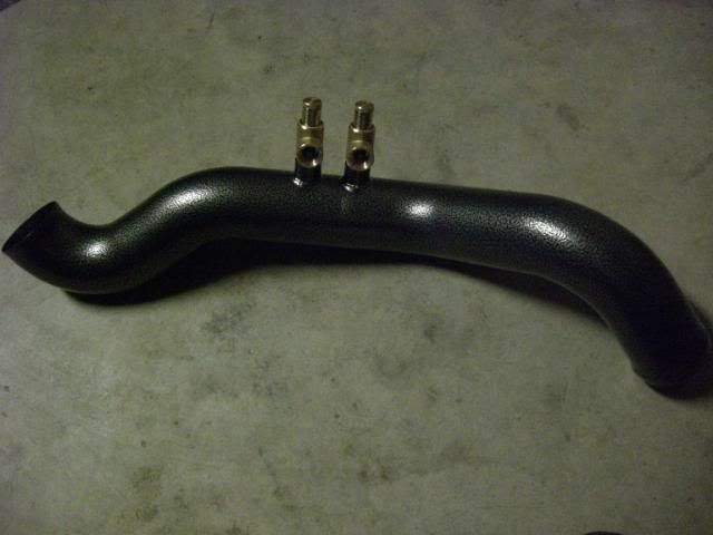
10. Apply never seize to threads of brass pop off valves, and thread into discharge pipe as shown below. Valves should ultimately be adjusted so that they face downward. This will insure that water or debris doesn’t collect inside the valves.
11. Install exhaust manifold using new gaskets shown below. The manifold will be installed upside down as shown below. Now is the time to install pyrometer probe into existing threaded ports on bottom side of manifold. If you choose to install the pyrometer on the top side of the manifold, the hole should be drilled and tapped with the manifold off of the vehicle. This will make it easier to clean shavings out of the manifold to prevent damage to turbos. Always use anti seize on pyrometer coupling threads.
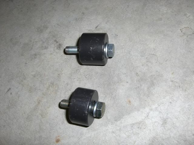
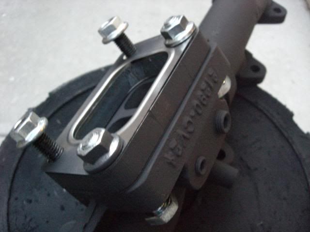
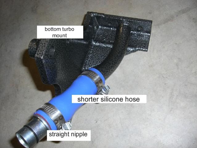
12. Install short (shorter of the two blue silicone hoses supplied with the kit) blue silicone hose onto bottom turbo mount bracket. Install straight nipple with o-ring onto blue silicone hose. (using glass cleaner, or soapy water may help slide the silicone hose into place). The bracket should appear as it does here:
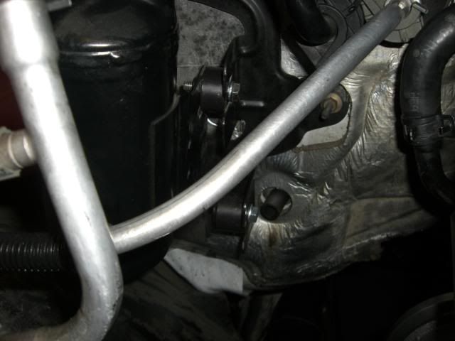
13. Use the two small bolts supplied in the kit to attach bracket with hose and nipple in place to primary (big) turbo as shown below.
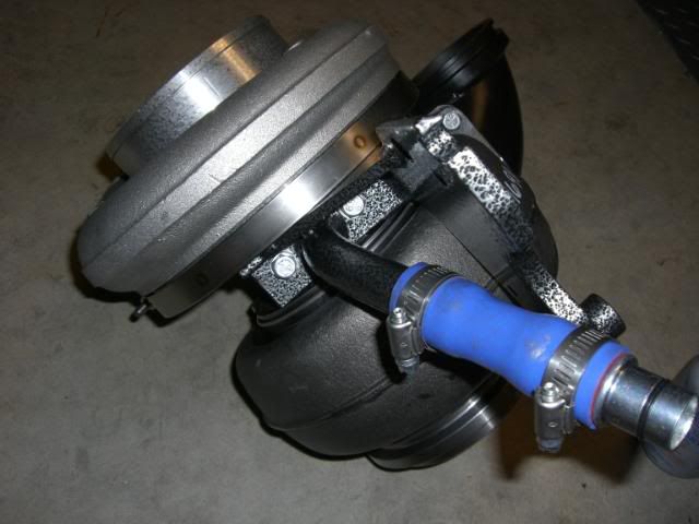
Make sure to use supplied gasket between bracket and turbo oil drain. Verify that mounting bracket does not contact v-band housing clamps, and that turbo shaft spins freely after tightening both small mounting bolts.
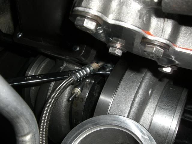
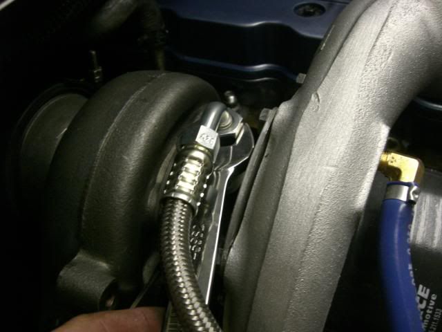
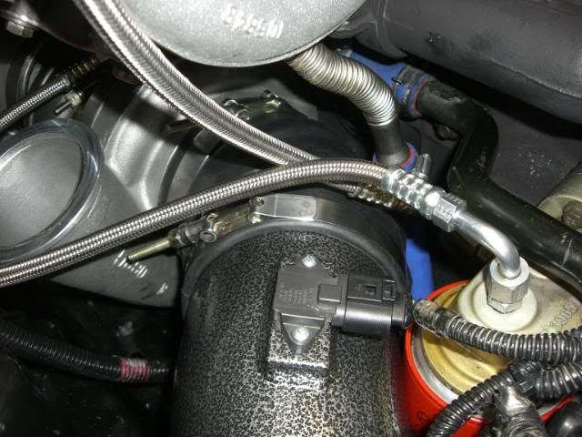
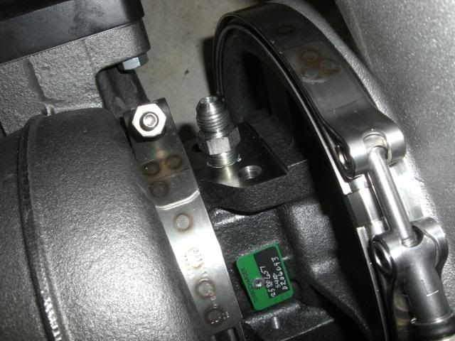
14. Install oil supply fittings onto both turbos as shown below.
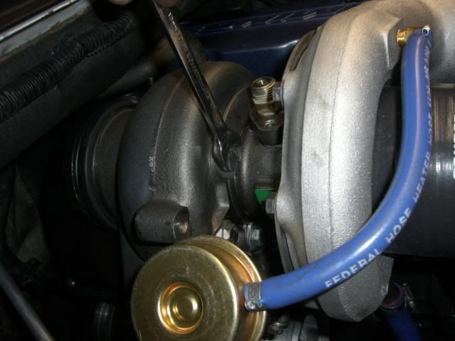
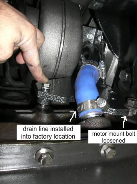
15. Remove upper motor mount bolt as shown below. Loosen lower motor mount bolt closest to firewall to allow bracket to slide over it.
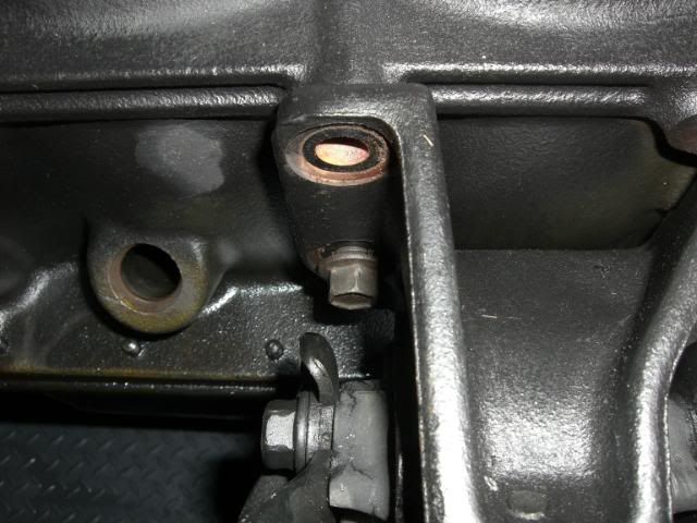
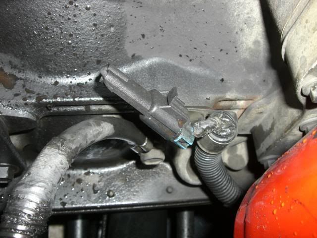
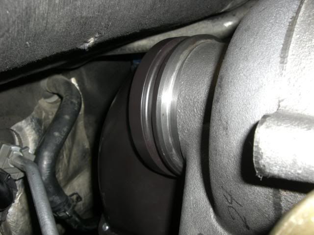
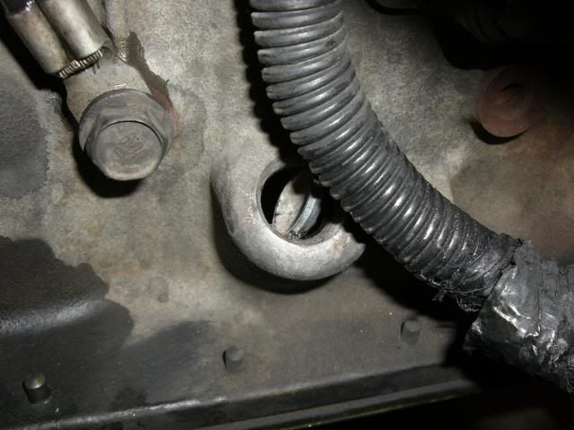
16. Remove factory soft plug from block. This port will be used for the top turbo oil drain. Using a very small flat screwdriver, GENTLY tap only one side of the plug until it rotates in the hole. As soon as it rotates, remove it using a pair of needle nose pliars. Again, only gentle tapping will be required to move the plug. All tapping should be concentrated on the same edge of the plug so that it rotates in one direction and is not pushed inside the block. Removal of the passenger side wheel/tire may make this step easier to complete. See illustrations below.
Plug before removal:
Plug tapped sideways, ready to be removed:
Plug is out, you can relax now.
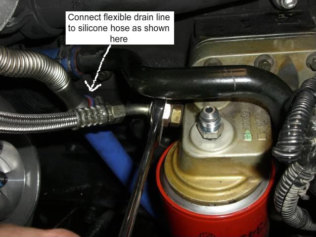
17. Install 90* oil drain nipple with longer section of blue silicone hose attached into block where soft plug was previously located. A small amount of clean oil should be applied to the o-ring on the drain line to help the line slide into the hole in the block.
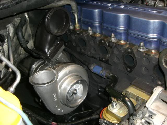
18. Lower primary turbo with hot-pipe and mounting bracket attached, onto loosened motor mount bolt. Insure that the turbo oil drain line has aligned with fitting in engine block, and install bolt into existing threaded hole in block. Reinstall and tighten upper motor mount bolt. Tighten lower motor mount bolt. Verify that turbo shaft spins freely.
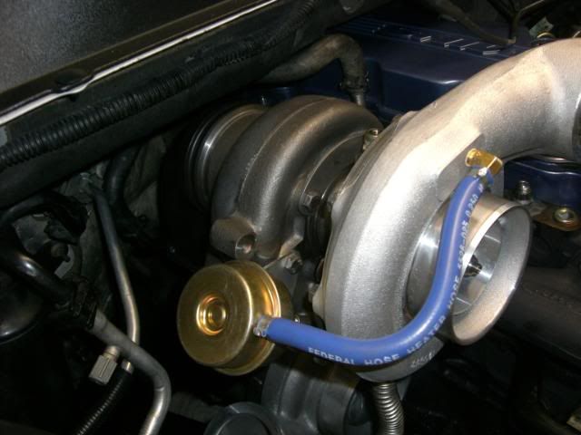
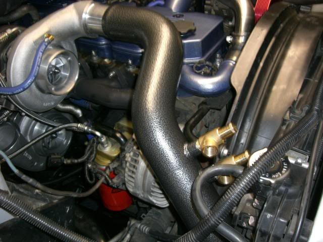
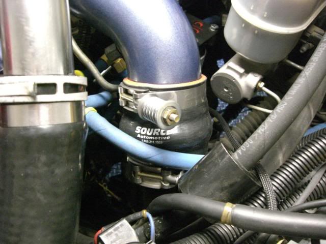
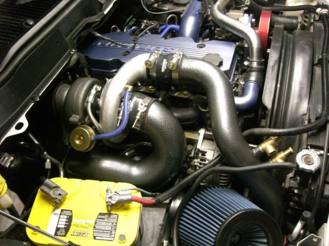
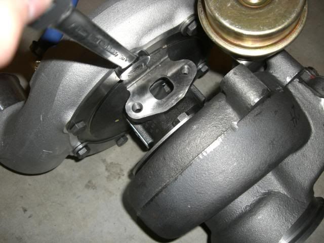
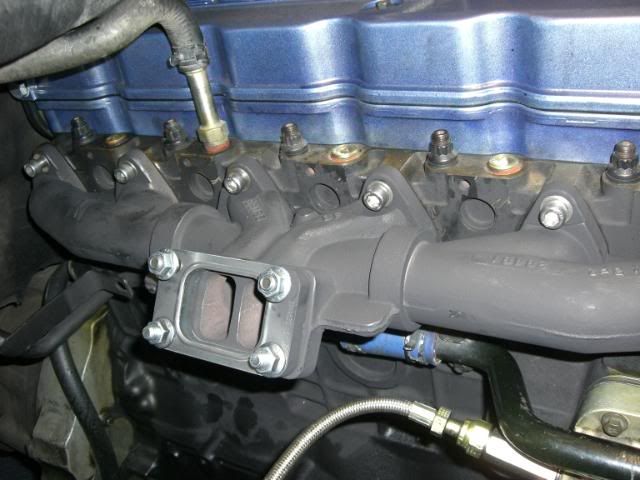
19. At this point, the turbo should be mounted as shown below.
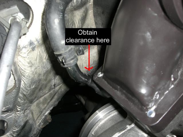
20. This is the appropriate time to verify clearance between rigid coolant pipe and hot pipe. Reshape rigid coolant line as needed to achieve proper clearance. (pic shown without manifold installed….. your manifold will already be installed.)
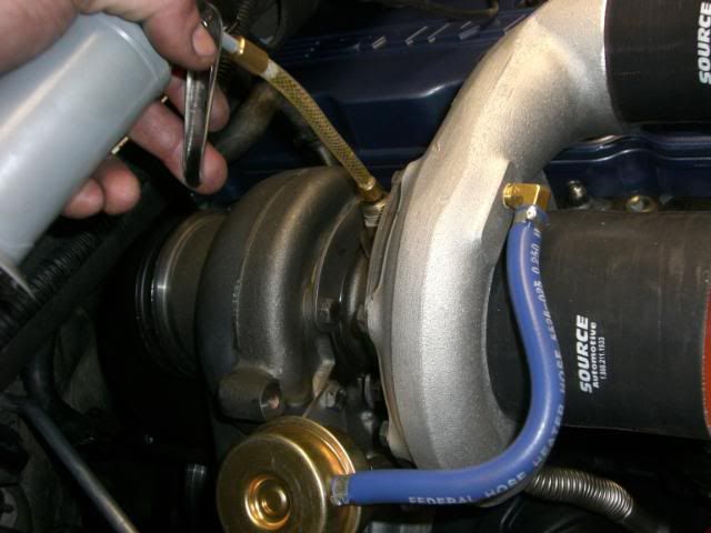
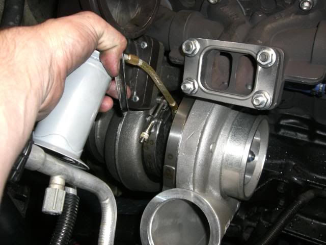
21. Fill bottom turbo with clean engine oil through oil feed line while simultaneously spinning turbo shaft by hand.
 ....................................................................see next post
-jp
Source Automotive Twin Turbo Installation Procedure, 2003-2007 Dodge, 5.9 Cummins Engine.
1. Open packages to verify that you have received all of the necessary parts.
2. Disconnect battery cables from both batteries, remove keys from ignition. Set parking brake. Failure to take these steps can result in serious injury or death!
3. Remove plastic inner fender as shown below. Several 8mm bolts hold it in place. There may be one or more plastic tabs used to hold wiring that will need to be detached from inner fender before it can be fully removed.
4. Remove existing turbocharger and exhaust manifold:
a. Disconnect and remove existing downpipe.
b. Remove existing intake/filter assembly.
c. By laying under the truck, firmly grip the turbo oil drain line and pull it out of the block. A bit of force may be required to pop the drain line out of the hole in the block.
d. Remove the braided steel oil supply line that runs to the top of the turbo.
e. Remove all bolts from exhaust manifold and pull turbo and manifold out in one piece. (help from another person may be necessary when lifting manifold/turbo out of engine bay)
Your engine should look something like this at this point:
5. Remove rigid coolant line from blue silicone hose to firewall shown in picture above. A bucket should be placed below the line to contain coolant lost when line is removed.
6. Using a piece of pipe and a rubber mallet, reshape the rigid line as shown in the following images:
Tap rigid hose with rubber mallet to slightly flatten the factory bend.
Slide a piece of pipe over the end of the rigid line as shown below, using the pipe to bend the rigid line into a shape that will clear the top turbo. After turbo is installed, additional adjustments may be needed. This took a first time installer less than 5 minutes to complete, it isn’t hard.
rigid coolant line before bending:
rigid coolant line after bending:
7. If you choose to paint your exhaust manifold, VHT flameproof paint works great.
Install the longer studs included from source automotive into the manifold. (the shorter studs supplied with the manifold will not be used) Apply never seize to studs. Install steel spacer and gaskets as shown below:
8. Loosen the compressor and exhaust housing clamps on the primary (big turbo) just enough so that the housings can be rotated as needed later in the install. Attach the hot pipe to primary turbo as below.
9. Remove secondary turbo (small turbo) compressor and exhaust housing bolts one at a time as shown below. Install never seize to threads and reinstall bolts loosely. This will allow the housings to be rotated to achieve proper alignment later in the install.
10. Apply never seize to threads of brass pop off valves, and thread into discharge pipe as shown below. Valves should ultimately be adjusted so that they face downward. This will insure that water or debris doesn’t collect inside the valves.
11. Install exhaust manifold using new gaskets shown below. The manifold will be installed upside down as shown below. Now is the time to install pyrometer probe into existing threaded ports on bottom side of manifold. If you choose to install the pyrometer on the top side of the manifold, the hole should be drilled and tapped with the manifold off of the vehicle. This will make it easier to clean shavings out of the manifold to prevent damage to turbos. Always use anti seize on pyrometer coupling threads.
12. Install short (shorter of the two blue silicone hoses supplied with the kit) blue silicone hose onto bottom turbo mount bracket. Install straight nipple with o-ring onto blue silicone hose. (using glass cleaner, or soapy water may help slide the silicone hose into place). The bracket should appear as it does here:
13. Use the two small bolts supplied in the kit to attach bracket with hose and nipple in place to primary (big) turbo as shown below.
Make sure to use supplied gasket between bracket and turbo oil drain. Verify that mounting bracket does not contact v-band housing clamps, and that turbo shaft spins freely after tightening both small mounting bolts.
14. Install oil supply fittings onto both turbos as shown below.
15. Remove upper motor mount bolt as shown below. Loosen lower motor mount bolt closest to firewall to allow bracket to slide over it.
16. Remove factory soft plug from block. This port will be used for the top turbo oil drain. Using a very small flat screwdriver, GENTLY tap only one side of the plug until it rotates in the hole. As soon as it rotates, remove it using a pair of needle nose pliars. Again, only gentle tapping will be required to move the plug. All tapping should be concentrated on the same edge of the plug so that it rotates in one direction and is not pushed inside the block. Removal of the passenger side wheel/tire may make this step easier to complete. See illustrations below.
Plug before removal:
Plug tapped sideways, ready to be removed:
Plug is out, you can relax now.
17. Install 90* oil drain nipple with longer section of blue silicone hose attached into block where soft plug was previously located. A small amount of clean oil should be applied to the o-ring on the drain line to help the line slide into the hole in the block.
18. Lower primary turbo with hot-pipe and mounting bracket attached, onto loosened motor mount bolt. Insure that the turbo oil drain line has aligned with fitting in engine block, and install bolt into existing threaded hole in block. Reinstall and tighten upper motor mount bolt. Tighten lower motor mount bolt. Verify that turbo shaft spins freely.
19. At this point, the turbo should be mounted as shown below.
20. This is the appropriate time to verify clearance between rigid coolant pipe and hot pipe. Reshape rigid coolant line as needed to achieve proper clearance. (pic shown without manifold installed….. your manifold will already be installed.)
21. Fill bottom turbo with clean engine oil through oil feed line while simultaneously spinning turbo shaft by hand.