Disassembly for rebuild has started.

jimbo486

New member
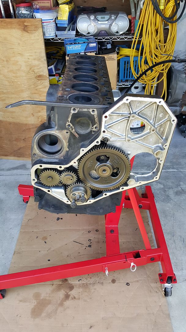
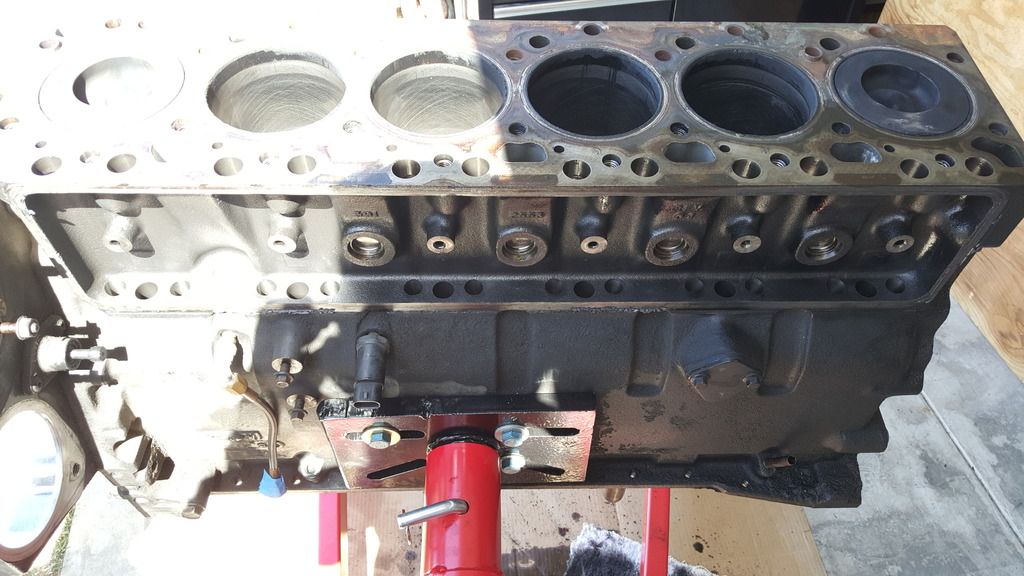
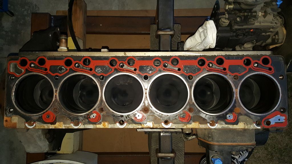
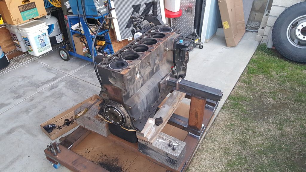
After building the stand/cart, I've been working on disassembly of my engine for the past few days. From what I can see, the head gasket didn't fail from excess boost pressure or advanced timing. It appears to be just a failure from a coolant passage seal next to cylinder #5 on the exhaust side.

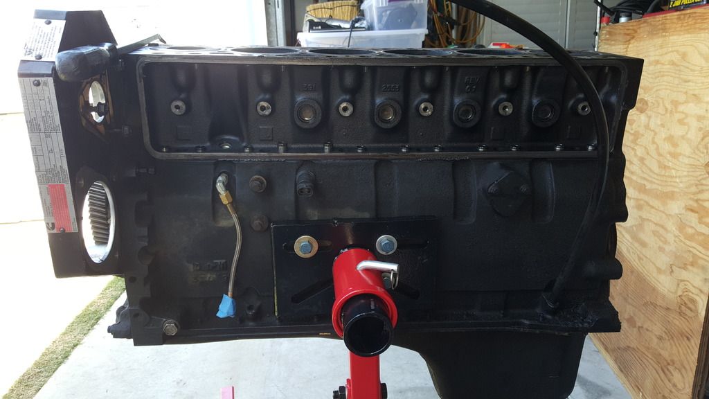
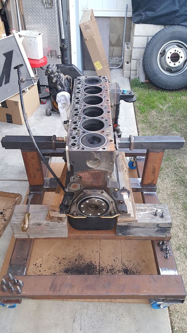
Between #5 and #6 is where the leak made itself known.

20160224_175158_zpsaubr9crz.jpg


20160224_175241_zpshisvzkis.jpg


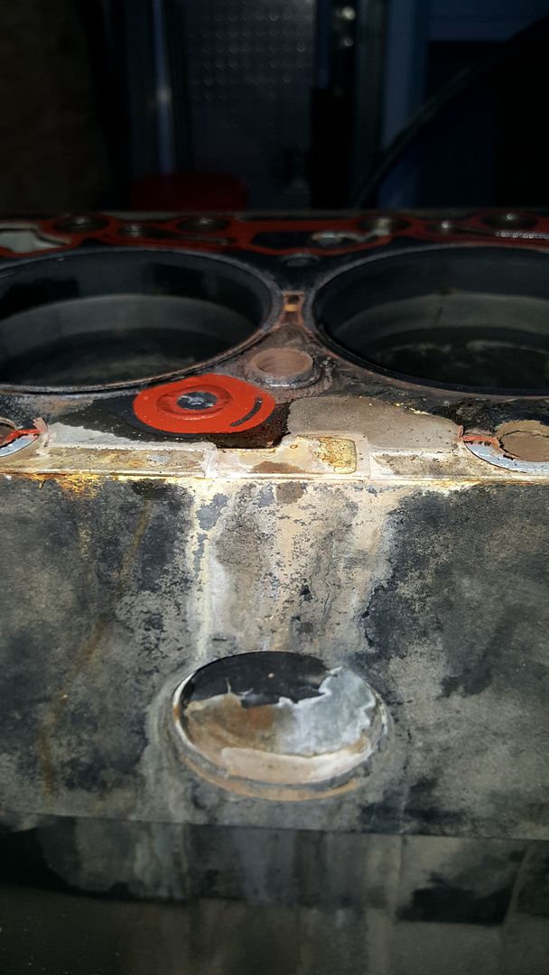
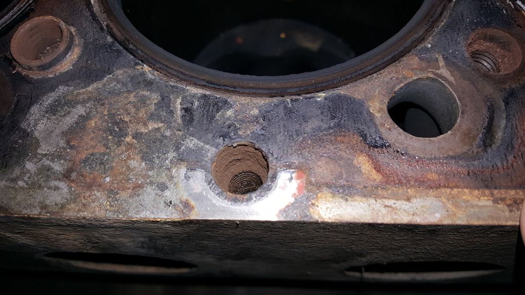
The suspected coolant passage next to #5.

20160224_180049_zpsqxmda84d.jpg


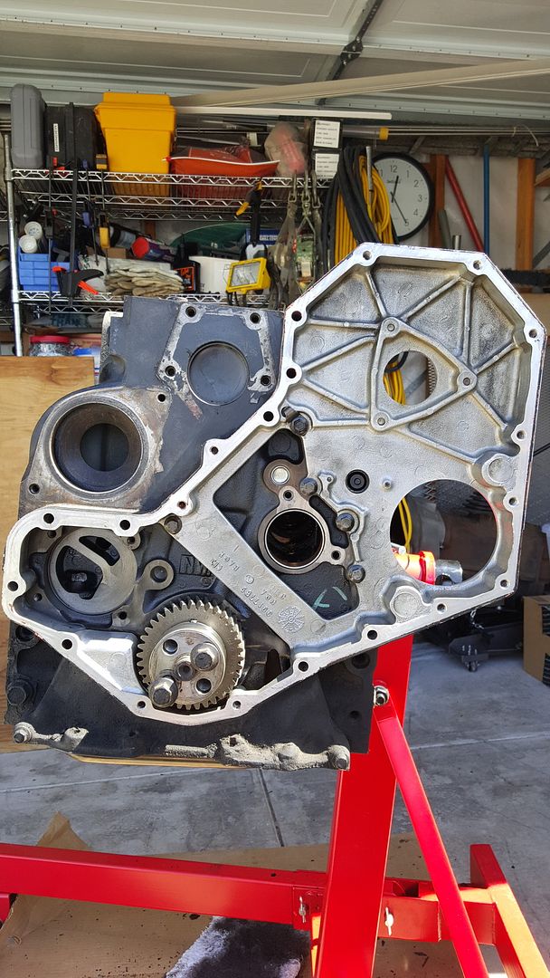
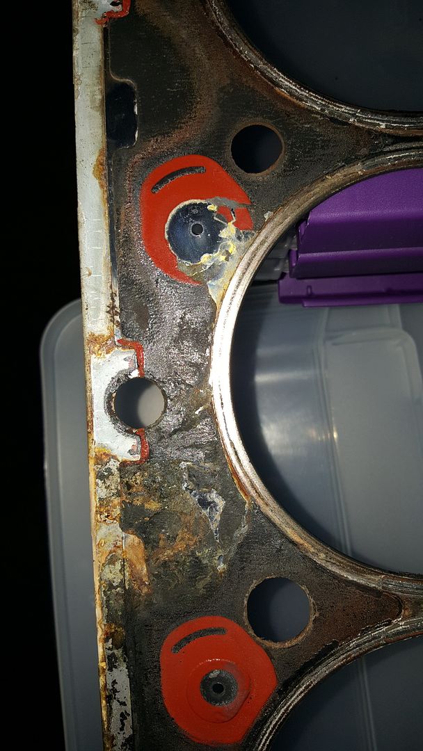
Block or bottom side of the gasket. It looks as though the coolant pushed out towards the cylinder and followed the fire ring around before going external below the exhaust runner. I guess some of the seal material missing would explain why I've occasionally seen small orange flakes in the coolant in the overflow bottle.

20160224_180231_zpsx93jyzeu.jpg


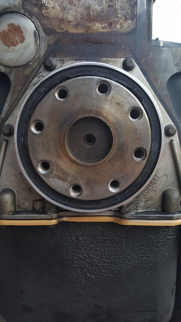
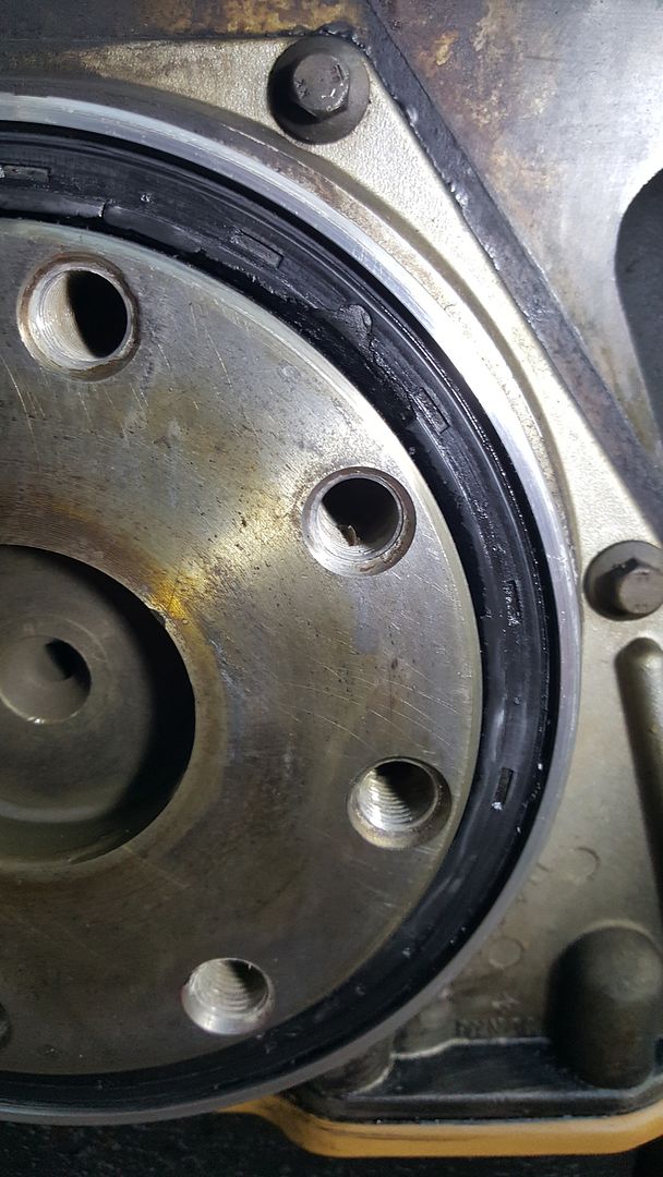
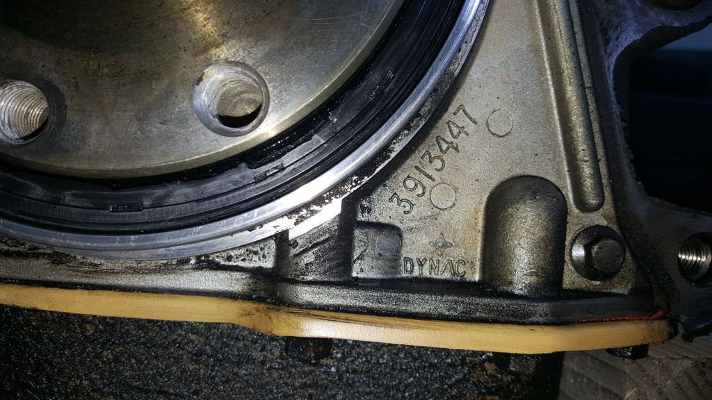
Flywheel, clutch disc and pressure plate assemblies removed along with the transmission adapter.

20160225_173549_zpsnkapdbto.jpg


20160225_173608_zpsemhlmxbi.jpg


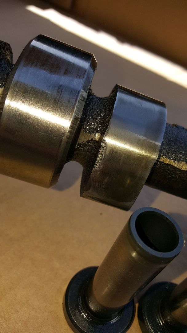
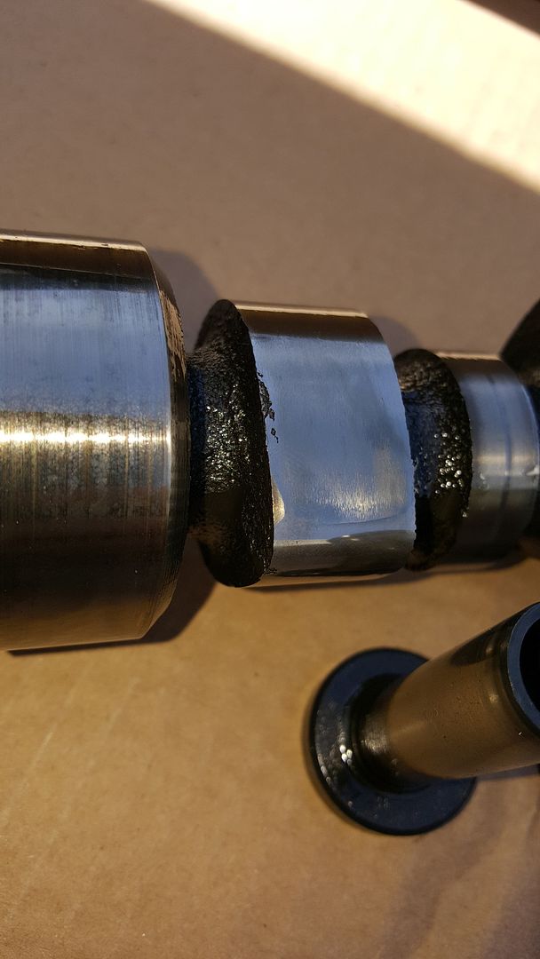
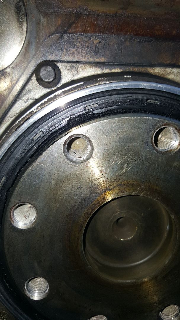
Strange finding the rear main seal with some pieces missing. However, it didn't leak. What could be the reason? Simply heat cycles from the engine caused the rubber to get brittle and break away? I installed this seal back in 2010 when the South Bend clutch went in. I used the supplied driver and had no issues during installation.

20160225_173649_zpsvimpoymm.jpg


20160225_173744_zps0kruth3p.jpg


20160225_173824_zpsuva1oc8a.jpg


20160225_173914_zpsfk3jttpk.jpg


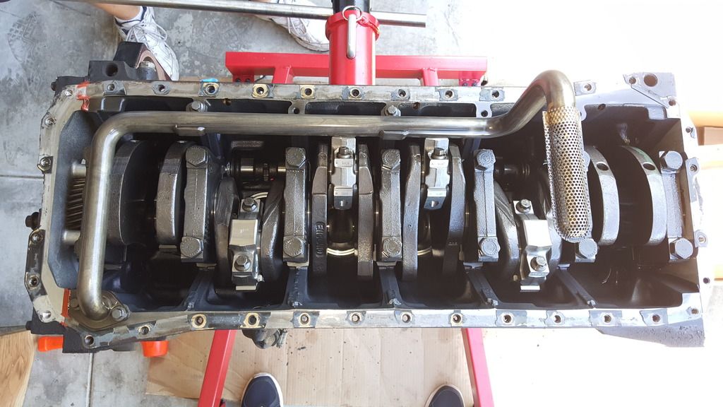
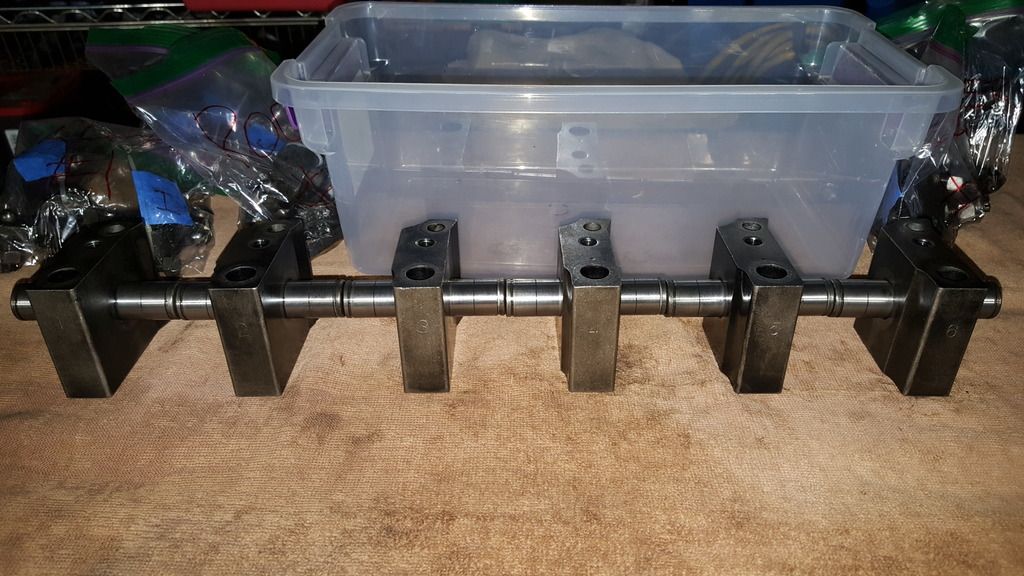
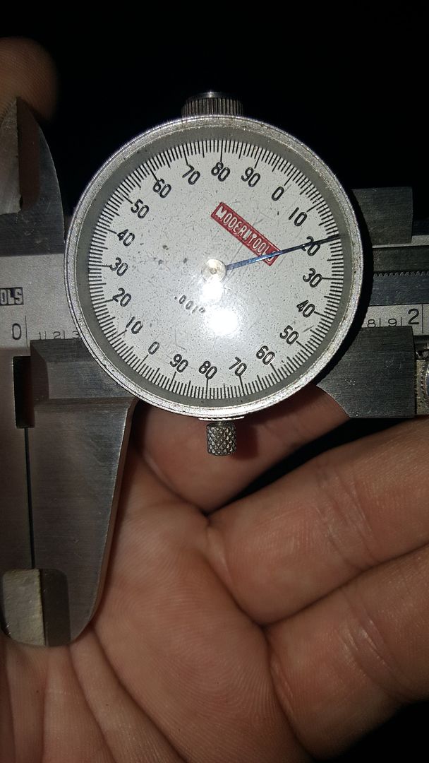
While not the proper way to check piston protrusion but it gives an estimate. Hamilton says for their cams to be truly bolt-in, piston protrusion cannot exceed .018". Since I don't have the dial gauge for checking protrusion, I'll lay a straight edge across the piston crown and check protrusion with feeler gauges to get a closer estimate.

20160225_181309_zpsuate1d2g.jpg
 
Last edited:
Disassembly continued today. For having clocked somewhere around 500k miles, I was amazed to find that the internals look great. With the exception of a few cam lobes having some imperfections. If it weren't for those and if I didn't know otherwise, I'd say the cam and tappets were new.

Injection pump removed.

20160309_110411_zpsrdfqdve6.jpg


20160309_110514_zpsho415psb.jpg


20160309_115132_zpszhzksq5m.jpg


Cam and oil pump out.

20160309_122507_zps9frmarsb.jpg


Tappets knocked out.

20160309_122537_zpsjxbowydk.jpg


I noticed some scarring on a couple of cam lobes. Not sure if this happened while pulling it out or what exactly. I wasn't forceful with anything at all. Later on, I noticed similar imperfections on a couple other lobes.

20160309_123855_zps3wskjr91.jpg


20160309_123847_zpsbicndzqm.jpg


Rockers disassembled for machining required for ARP studs.

20160309_190505_zpsichftmcs.jpg
 
Cool post, looks like it's coming along good. I have yet to see a seal break away like that but the inner part of the seal is what holds your oil in is why you didn't have a substantial amount of oil loss.
 
The cylinders are getting bored .020" over. Crank and rods checked out good and will get standard bearings.

Strange thing about the oil pump I bought. The body of it doesn't match the old pump or the receiver bore in the block. The machine shop came up with 3.31" as an OD on the new pump. The old pump, I measured and came up with 3.43". Nearly an 1/8" difference.

I bought the higher flowing (and pressure?) Cummins pump that is said to work for any '89-'02 engine. Is this acceptable or what? I'm inclined to exchange it for the exact replacement of the old one.
 
You did blow the gasket btw. That's why it looks like if blew towards the cylinder. Comment when they blow
 
I bought the higher flowing (and pressure?) Cummins pump that is said to work for any '89-'02 engine. Is this acceptable or what? I'm inclined to exchange it for the exact replacement of the old one.
Run the later, higher volume pump. Your existing pressure regulator will maintain the pressure you're use to seeing.

I run it in mine with no issues.
 
You did blow the gasket btw. That's why it looks like if blew towards the cylinder. Comment when they blow

Thanks, Austin. So then 2, 3 and 4 were close to it by the looks of the top side of the gasket. Those pieces of the seal weren't stuck to the head when I looked. I'll have to look at the block side of the gasket on those ones.

Run the later, higher volume pump. Your existing pressure regulator will maintain the pressure you're use to seeing.

I run it in mine with no issues.

I used the part number that Cummins Performance Parts provided on their website. Supposedly, some guys were getting bad pumps from CPP some time ago? Therefore, Cummins must have had a bad batch at one time. Or the pump number is incorrect altogether? Cummins P/N for reference is 4939587. Didn't supersede at Cummins when I ordered it.
 
Last edited:
We had a small batch that failed and no problems since we sent them back and got a new batch of pumps. No more issues that we have seen.
 
I was wondering about having an aluminum or stainless steel sleeve made to make up the differences. Is it even worth the hassle? Why would the body be a smaller diameter than the receiving bore in the block? Surely that can't be how higher flow was accomplished. Seems like the flutes in the stator would be opened up to create more flow. Maybe I'm wrong in my thinking.

Anyhow, the head is done and was shipped out today. Hamilton 165lbs. springs, 3-angle valve job and o-rings using .062" stainless steel wire. The machine shop is just waiting on parts. The block should be done before the end of next week.
 
Last edited:
As for the head studs, is bottom tapping necessary for clearing the valve covers only or both that and more thread engagement and clamping force? The instructions say it's necessary, for the rocker arm head bolts anyway, if "the location of the rocker arm pedestal head studs are above the specified installed height of 6.615-6.665 in."

There's no other mention of bottom tapping the rest of the holes but I see the recommendation of doing so here all the time. I assume for even clamping across the entire surface? I was going to have the machine shop bottom tap the holes for me but held off until I could measure the installed height since it sounds like not all engines will need bottom tapping. Just looking for confirmation but I think the recommendation is bottom tapping ALL of the holes.
 
The pedestals have been machined. Is the recommendation to bottom tap ALL holes or just the ones for the pedestals as ARP says? I think I'd prefer to do all of them to keep it uniform.
 
I'm not 100% sure but I don't believe you need any clearance for the studs if they require the rockers to be machined??? And from what I have always been told for each size bolt there is a certain amount of threads that are needed for maximum holding strength of the bolt so any more threads doesn't really help you any but I guess it doesn't really hurt at the same time.
 
The instructions say bottom tapping is necessary for the rocker arm head bolt bores if "the location of the rocker arm pedestal head studs are above the specified installed height of 6.615-6.665 in." That dimension is from the deck of the block to the top of the stud.

I'll call ARP tomorrow.
 
If you don't bottom tap the studs will all be protruding at different heights. A different amount of threads will show on each stud with the nuts tight. It's easy and takes 20 minutes. Fastenal got me a tap, just get the longer one.

Call me ocd or whatever but I couldn't stand to look at them expensive studs if they weren't all equal with the nuts tight lol
 
Last edited:
Back
Top