New Pro Stock Diesel build - 2 D Max

What should Michael name his new truck?

  • 2-D-Max

    Votes: 40 60.6%
  • 2wD-Max

    Votes: 7 10.6%
  • Something else (please post ideas)

    Votes: 19 28.8%

  • Total voters
    66
If I can suggest a feature (you may already have this) but have time as recording (not actual clock time, just a counter). This will make it much easier for those of us trying to match up these graph's with other data logging graphs. Something that we can display on the X axis.
We do have a counter that just starts at zero when the log starts and increments in seconds. Since there is no real-time clock on the system we can't do much else. Would it help to be able to reset that "time" value to be zero at a specific part of the graph?

Can anybody say SKILLS.......
LOL, more like I'm just too dumb to let someone else do the hard work! I do hope that someone else can learn from some of the mistakes I have made on this build.
 
Would it help to be able to reset that "time" value to be zero at a specific part of the graph?

It seems like that would be most beneficial. Its really handy with our drag cars (using racepaks) to be able to reset the start time off of the accel g's to time out the pass as close as we can to help see whats going on at what part of the track. And also overlay them with other logs.
 
It seems like that would be most beneficial. Its really handy with our drag cars (using racepaks) to be able to reset the start time off of the accel g's to time out the pass as close as we can to help see whats going on at what part of the track. And also overlay them with other logs.

Thanks! Unfortunately we just completed a software update (the one to ship with the initial dataloggers), but I will add that to the "wish list" for the next update. We did get in the other "wish list" items from the users of the existing dataloggers, such as storing the custom labels for each channel, and an easy way to turn the viewing of the channels on & off on the view screen.

Regards,
Michael Pliska
 
Episode 18:
Starting with a pile of parts, the strut bases need to be pressed on with dowel pins, then the steering arm is secured with a stud which passes all the way into the strut body. There are also two 3/8" bolts which thread into the base and prevent the steering arm from turning (and also give it some support from bending). As I followed the instructions of adding Loc-Tite and torquing both the stud and the bolts, I ran into a couple of issues.

First up, the stud was too deep to use even my deepest sockets to reach the 7/8" hex. Fortunately I had a 7/8" crowfoot flare nut wrench which I bought for changing the fuel bowl heater on my Powerstroke! When torquing with a crowfoot, remember to take the extra leverage into consideration. For example, if the crowfoot moves your pivot point 2.0", you multiply the required torque by 12/(12+2). As I went to torque the smaller bolts I discovered they had 5/16" 12-point heads, which isn't one of the options in most socket sets! Fortunately my Powerstroke specialty tools saved the day again, as I had purchased one (and had it stashed with my "special" sockets) to use on the 8mm 12-point bolts holding the downpipe to the turbo. I did discover that the bolts were too long for the holes, and they actually bottomed out about 0.080" before becoming tight. Be sure to check little details like that when building a race car/truck, at a glance it might have gone unnoticed! I was going to add washers, but decided to make lemonade out of the lemons, I will space them up with a separate bracket I will add later to anchor a front suspension travel limiter. I was trying to decide where to mount such a bracket anyway, so this made the perfect solution!
DSCF1830_zps158baf9c.jpg


The Chassisworks strut kit includes a 4130 Chrome Moly strut bottom piece, which holds a spherical bearing for the bottom of the strut, and the rear control arm bar welds to it (so it effectively becomes part of the lower control arm). I had to temporarily press the spherical bearing into place for fit-up, but it will be removed later for the welding on that part. The installation instructions warn you more than once: DO NOT EVEN THINK ABOUT WELDING WITH THE SPHERICAL BEARING IN PLACE! (or words to that effect)...

DSCF1846_zpse933c360.jpg


I installed the hub for that side, since that is what is going to mount to my jig holders for positioning the strut assemblies.

DSCF1847_zpsb5a3cea4.jpg


The other ends of the control arms are threaded ends with spherical rod ends. I installed the ends at the midpoint of their usable adjustment, then measured the lengths of the tubes for the lower control arms.
DSCF1860_zps2864d7dc.jpg


This was easier said than done, as the whole mess moves around in 3 dimensions but the strut top, hub center and angle needs to be precisely positioned. I ended up just placing the overlength tubes in place and measuring the distances from the mounting holes
DSCF1861_zps637cfe1b.jpg


After cutting the tubes to length I mocked it all into place, adjusting over and over until I had everything positioned and angled correctly. I was nervous cutting the control arm tubes until I realized they were just 1" x 0.058" tubing (I had a bunch of it for other parts of the chassis in case I screwed up).
DSCF1864_zps2e260a97.jpg


At this point I realized that the front strut support bars would be passing very close to the front control arm mount (which was just tack welded into place at this point). As I confirmed that its position and ange were perfect in positioning the strut assembly, I finish welded it and added a gusset.
DSCF1872_zps0161ef93.jpg


I made sure to set the strut angle at 10° backwards, setting it up for a positive caster alignment.
DSCF1869_zpsce9de100.jpg


The next detail was to hold the strut at the exact "at rest" position that I wanted. This is one of those situations where building a truck rather than a car, and picking some unusual components can lead to some variations from the "generic" component instructions. I went with the longer (4") stroke struts, and the overall geometry was a bit different being a truck. The instructions that came with the struts would have had me installing them about 3" above the fully compressed position, which would have been more appropriate for an off road racer than a drag truck! A phone discussion with the manufacturer confirmed that I should be at 1" to 1.5" above fully compressed. I went with 1.375" above the fully compressed position, and cut some sections of fence post tubing to the exact length to hold the struts at that height. I cut a slot in each piece so they could be easily slid in and out of the assembled strut.
DSCF1870_zps87b4248f.jpg


I did not have the luxury of readily replacing a screwed up cut when it came to the main strut support tubes, which have a bend (which I already did at my friend's chassis shop) and are quite long. If I screwed these tubes up I would be buying another 20' length of tubing, then running to my friend's shop to bend another one (a big wasted of time & money). As a result I roughed the cuts and notches in initially too long, then worked it down to the correct dimensions. In other words, measure 10 times, cut 5 times...
DSCF1875_zps3e0c6197.jpg


With weld draw as a possible issue, I did several VERY small tack welds to help hold things in place (and went back and checked position several times), then proceeded to stitch weld the ends of the tubes to the chassis. Since my electric heaters could only bring my garage up to about 39°, I made sure to preheat the weld areas with a heat gun.
DSCF1879_zps639019fc.jpg


The upper strut cup mount could only be lightly tack welded while having the upper spherical bearing in and attached to the strut (to prevent strut and bearing damage). I measured the angle of the mounting plate to make sure it remained unchanged as I disassembled and welded on it.
DSCF1882_zpscd399d9d.jpg


After removing the strut I used some sockets and a C-clamp to press the spherical bearing out of the mount.
DSCF1880_zps0c53fbf4.jpg


Of course no matter how careful I was with the C-clamp, I managed to tweak the angle of the mounting plate, but at least it was easy to bend it back to the original angle.

I tacked in one side gusset to the mounting plate to help hold it while I stitch welded the plate into place.
DSCF1884_zps9c62e6aa.jpg


I then proceeded to stitch weld the strut top mount, as well as both ends of the strut bars, then added the 2nd side gusset to the strut mounting plate. I mentioned previously about drilling air holes to relieve pressure when welding on shorter sections of tubing. I figured this section of tubing was long enough to not need it, but since I was alternating my welds on both ends AND the center, it still got hot enough to blow out while I was laying a bead!
DSCF1887_zps96cc9e4d.jpg


Aside from that I was able to get things anchored down pretty well, and everything was positioned exactly where it was supposed to be. I wanted to make sure to have the chassis as stable as I could, due to my next plans... Hmm, what could those be?
 
I'll post up more photos soon, hoping to run back to the plant today and weigh it (I put it in the ISSPRO plant until I'm done racing my gasser for the year).

Have you weighted it??
What kind of scale did you use and what was the result??
Post here all about it i am interested to know about it.
 
I have been used industrial scales and floor scales for such purpose. I have an interesting fact in my life that is to know core features of any thing that i have and also to know about is physical properties. So whenever i bought something i must try to know about its weight.
 
No offense, but people need to graduate from photobucket LOL. That bandwidth exceeded crap is for the birds. I like to see pictures too!
 
Episode 19:

After that thrilling cliffhanger I'm sure you were all wondering what was next? Okay, maybe "thrilling cliffhanger" is really "slightly more interesting than someone's Grumpy Cat Internet Meme"...

I had discussed with my employer (ISSPRO) the possibility of bringing the chassis to work. This would serve two main purposes:
1) I could sneak back on breaks and get in some work on it during the day, and
2) I could avoid the inevitable frostbite-countering warm-up breaks from working in my freezing garage, and the potential of toe amputation from said frostbite.

In addition, I would have more workspace (it was starting to get cramped as the chassis is growing to full length), I could use the forklift for lifting & rotating the chassis to weld underneath, I could use one of our Bridgeport mills for machining brackets, and I could pick my daughter up from school in the afternoons (I'm a single dad with custody) and come back to work on it in the evenings. The plan was to work while she does her homework in a nearby office and I am available to verbally help her while continuing the fabrication process. That last part hasn't worked out quite as well as planned, with Caitlyn usually wanting to hang out in my office (where she spends more time doodling on my whiteboard than actual homework).

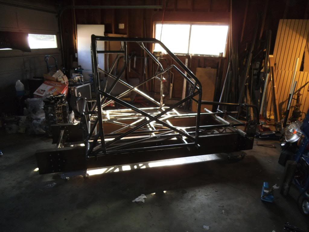
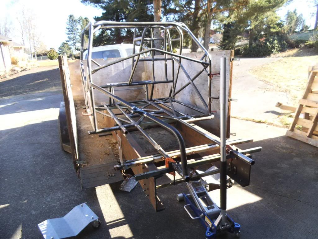
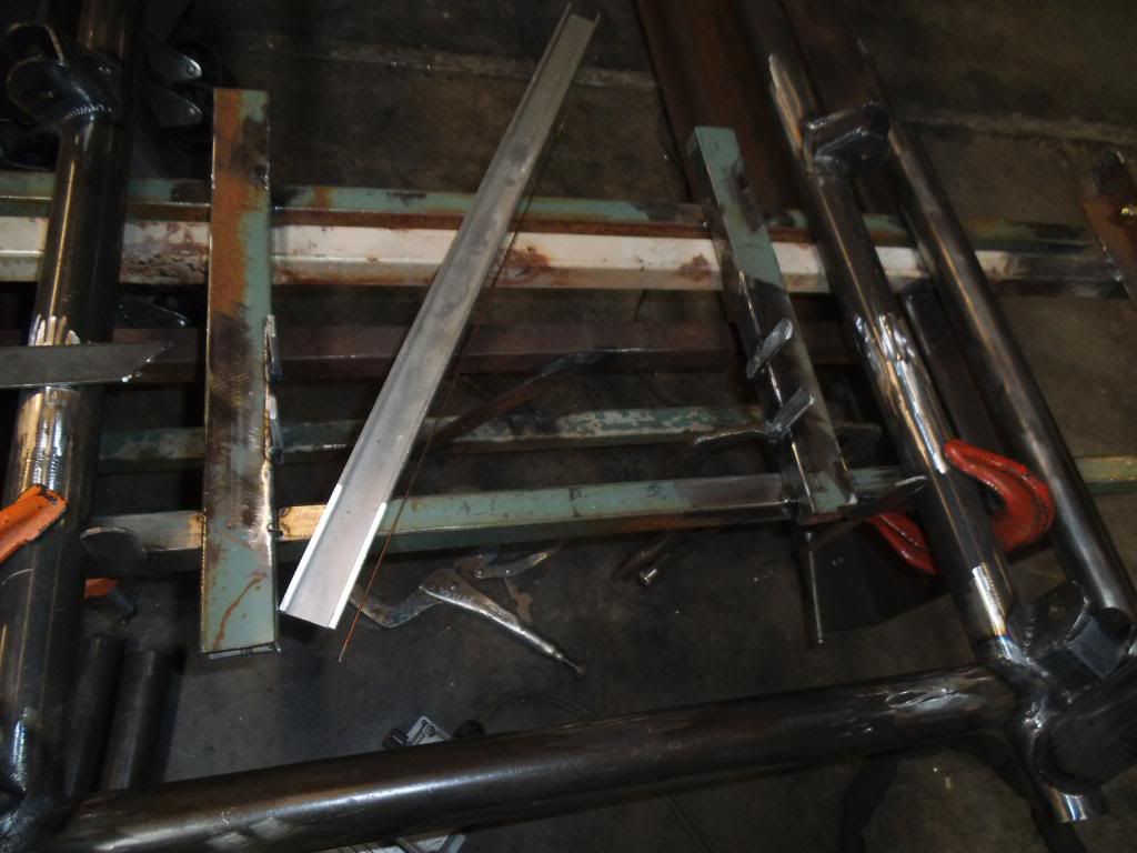
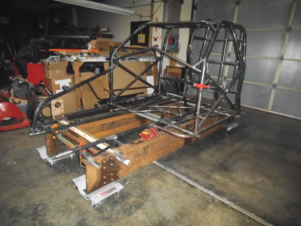
I decided to transport the chassis & the jig clamped together, figuring the chances of both making it intact would be improved with each reinforcing the other. Of course it also meant trying to move a nearly 2000 lb bunch of steel without wheels by myself! I jacked it up in my garage and placed it on wheel dollies:

DSCF1888_zps680d5d49.jpg


I considered transporting it in my enclosed trailer, winching it up the ramp door, but my sloping lot would require me to get it up my steep driveway first (and I was working alone on a rather cold day). I decided to use my flatbed trailer with sideboards on to help hold in all the other crap I would be bringing.

I wheeled it up to the trailer, then used the floor jack to get the 1st end onto the trailer.

DSCF1889_zpsdccd84f2.jpg


I forgot to take a picture of it, but I had previously been using the trailer for hauling firewood, and hadn't cleaned out the small pieces in a while. They formed a pretty big layer on the floor of the trailer, which was now frozen solid. I ended up spending an hour in the freezing weather chipping away at the pile so I could see the floor again.

At this point I used an old trick from moving safes out of grocery stores (dismantling the stores, NOT stealing the safes ;) 
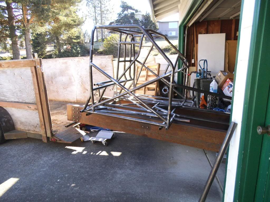
). I used a couple of pieces of tubing as rollers, between the jig and the floor of the trailer. This was why I had to get the floor cleaned up!

Once I had the 1st roller up there it was relatively easy to push it up by hand.

DSCF1890_zps582e01dd.jpg


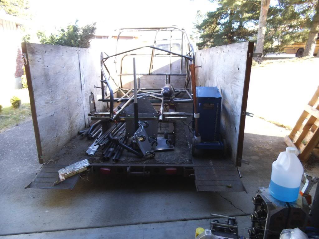
After tying the jig & chassis down I packed in all of the remaining tubing, plus my welder, Argon bottle (securely strapped to the chassis), and a bunch of other tools.

DSCF1891_zpsf138f453.jpg


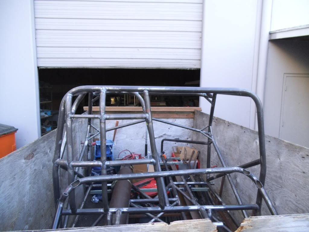
Of course the door to the spot where they cleared out for me to work on it was a pain to get to (one of those spots where it takes a complete jacknife of the trailer), but I did it.

DSCF1892_zps8dbe45e4.jpg


Unloading was just a reverse of the loading process. I thought about using the forklift, but it would have meant effectively "painting myself into a corner" backing the lift into a spot up against some machinery.

DSCF1893_zpsb3ebb089.jpg


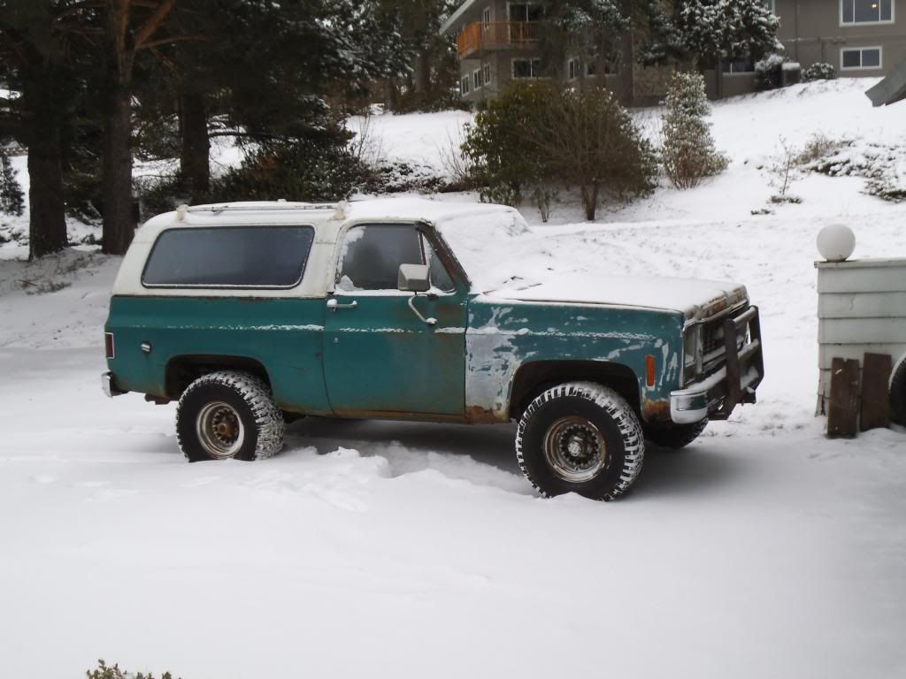
Of course my luck with this project continued. The next morning after moving the chassis and tools, there had been a forecast for possible light flurries. Instead what we got was a 5 day "Snowpocalypse", which would have barely slowed a Northern or Midwestern city but paralyzed our city. My plan was to use my old '73 Blazer to get into work (if it got too deep for my Jetta with snow tires & chains). I verified that my Jetta could not make it on the hills around my house and turned to the formerly trustworthy Blazer. That night I parked it with its nose and windshield under the overhang of my camper, thinking I was being smart and keeping the snow off of it. When I went to fire it up in the morning it would not start, and it was so pinned in that I could barely open the hood. After pushing it back as far as I could by hand, I was able to swap a bigger battery in, and discovered that it was not getting spark. It turned out to be a failed electronic ignition module (GM HEI distributor), and with the Pontiac 400 engine swapped into the Blazer it is a VERY tight fit working on that distributor even if you can get the hood all the way open! I was able to replace it working by feel (crammed into the claustrophobic space under the barely open hood). By this point I had burned up 3 days of the Snowpocalypse, spent another day sledding with my daughter to make up for it, and finally got to work on the chassis again!

DSCF1902_zps5e012af4.jpg


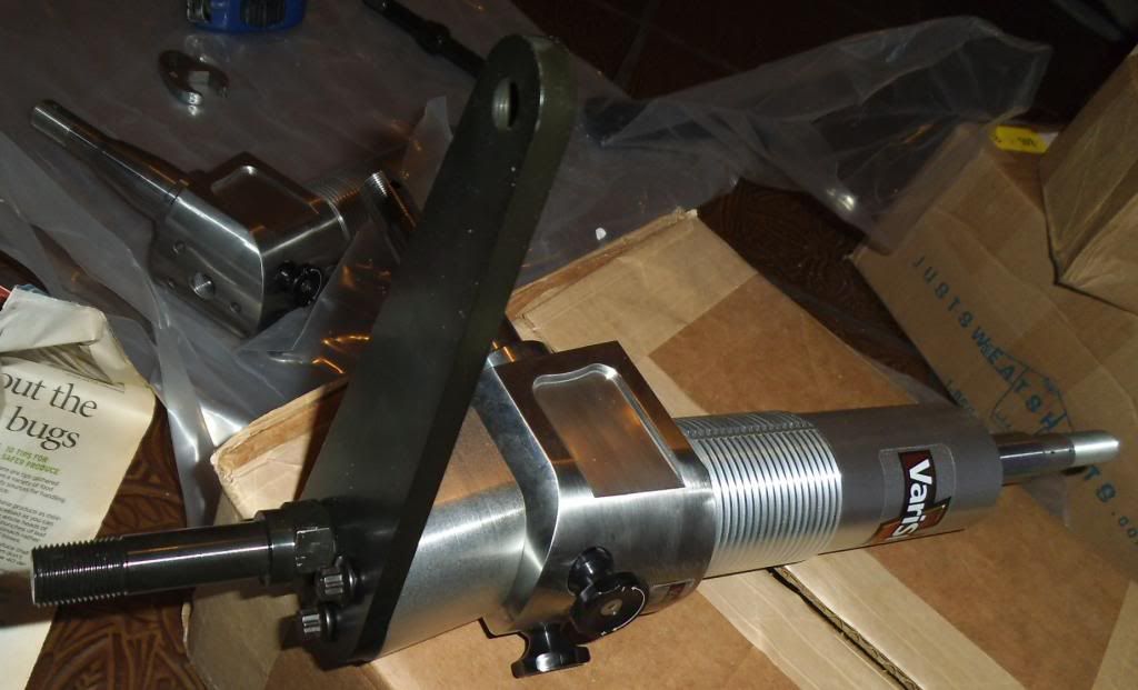
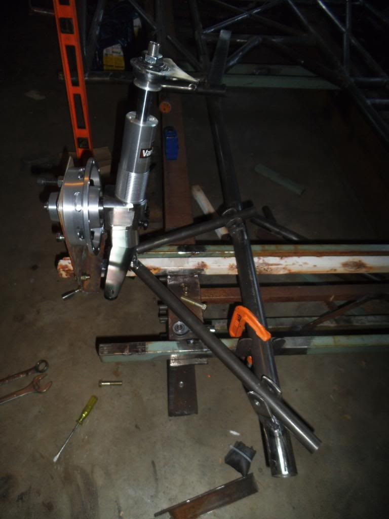
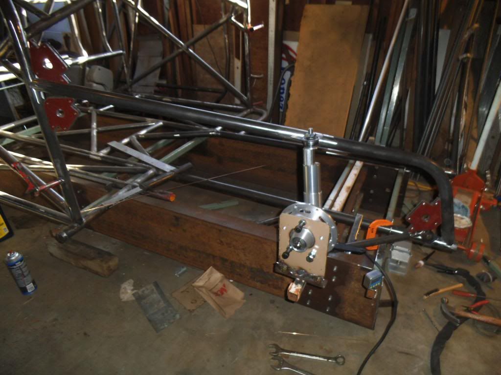
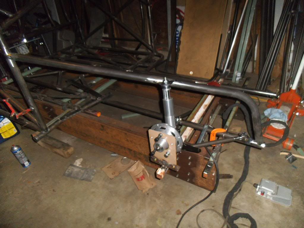
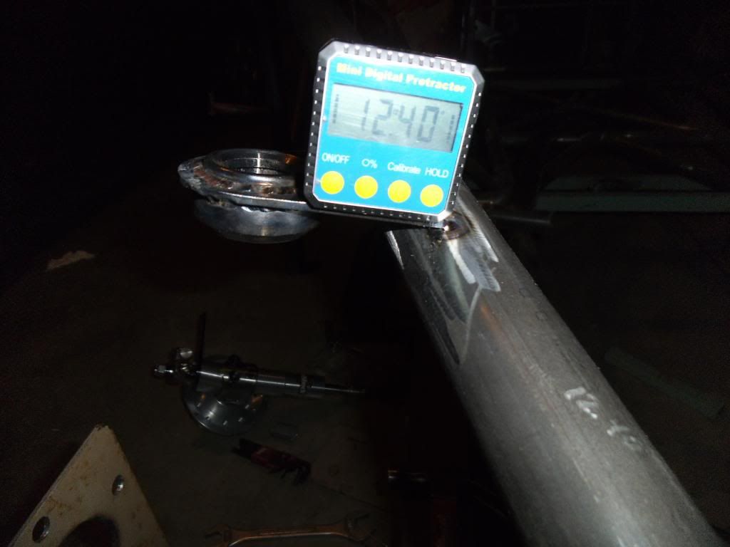
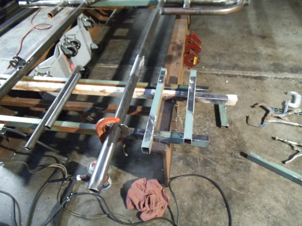
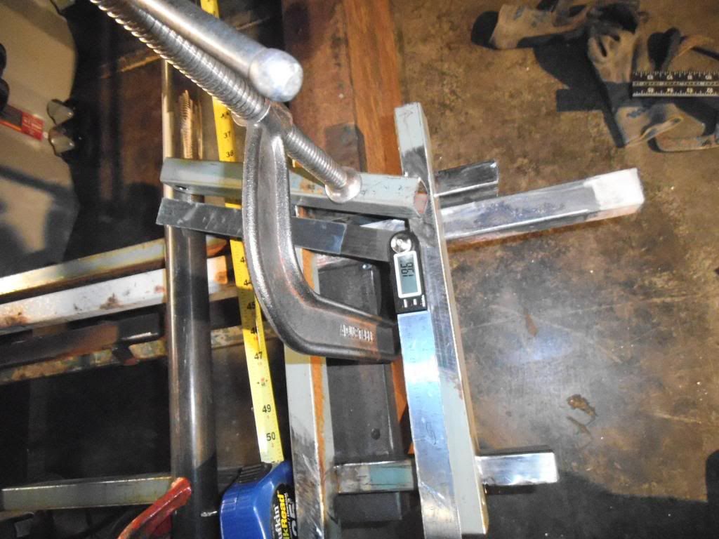
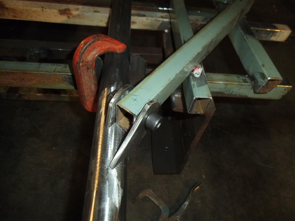
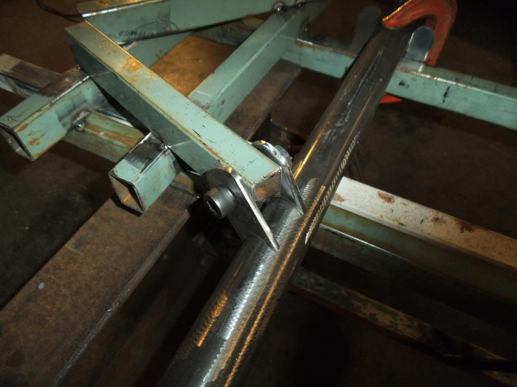
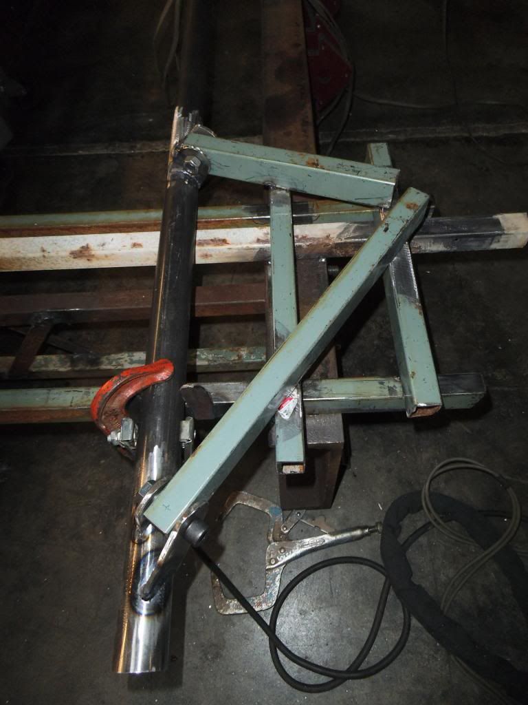
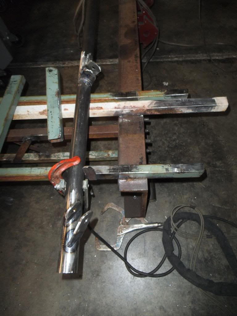
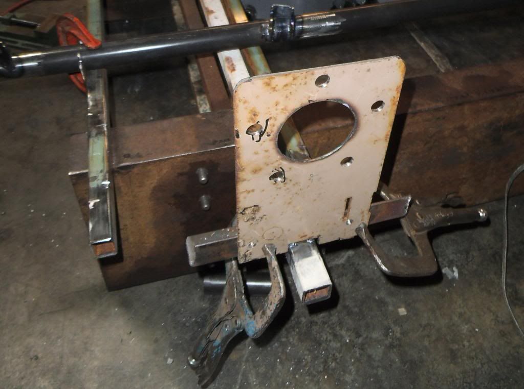
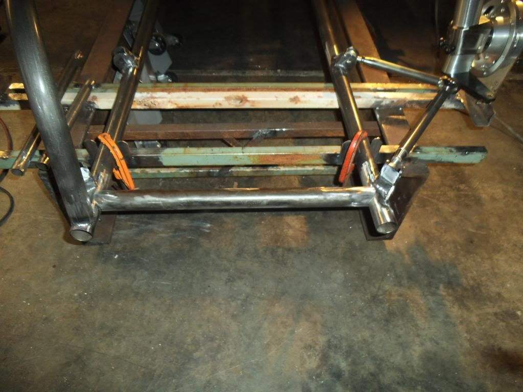
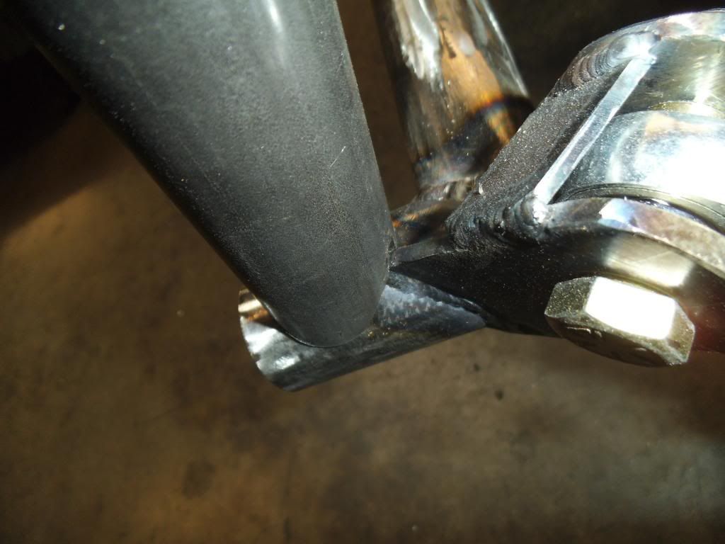
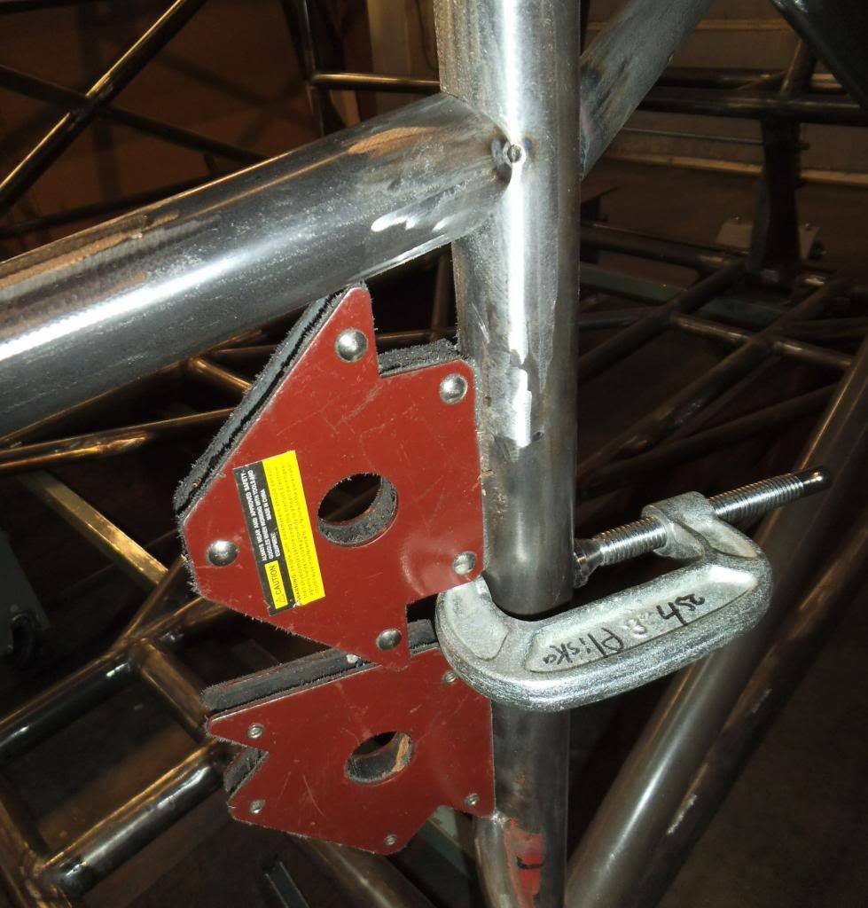
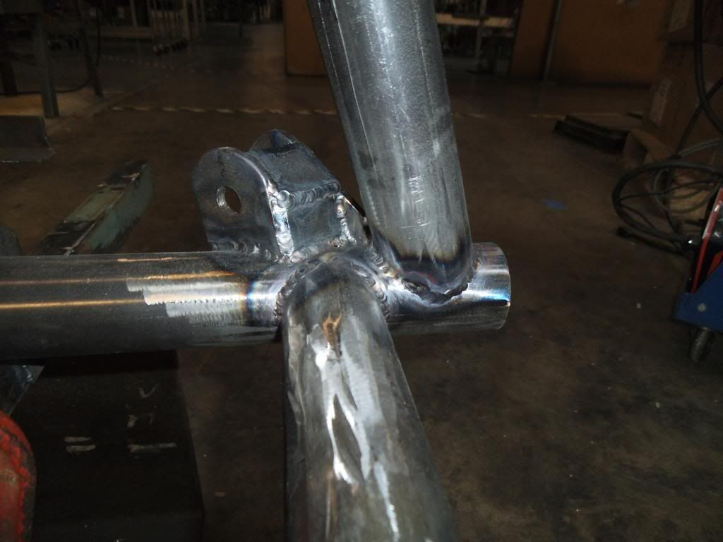
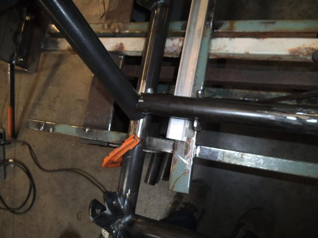
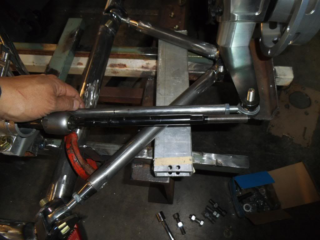
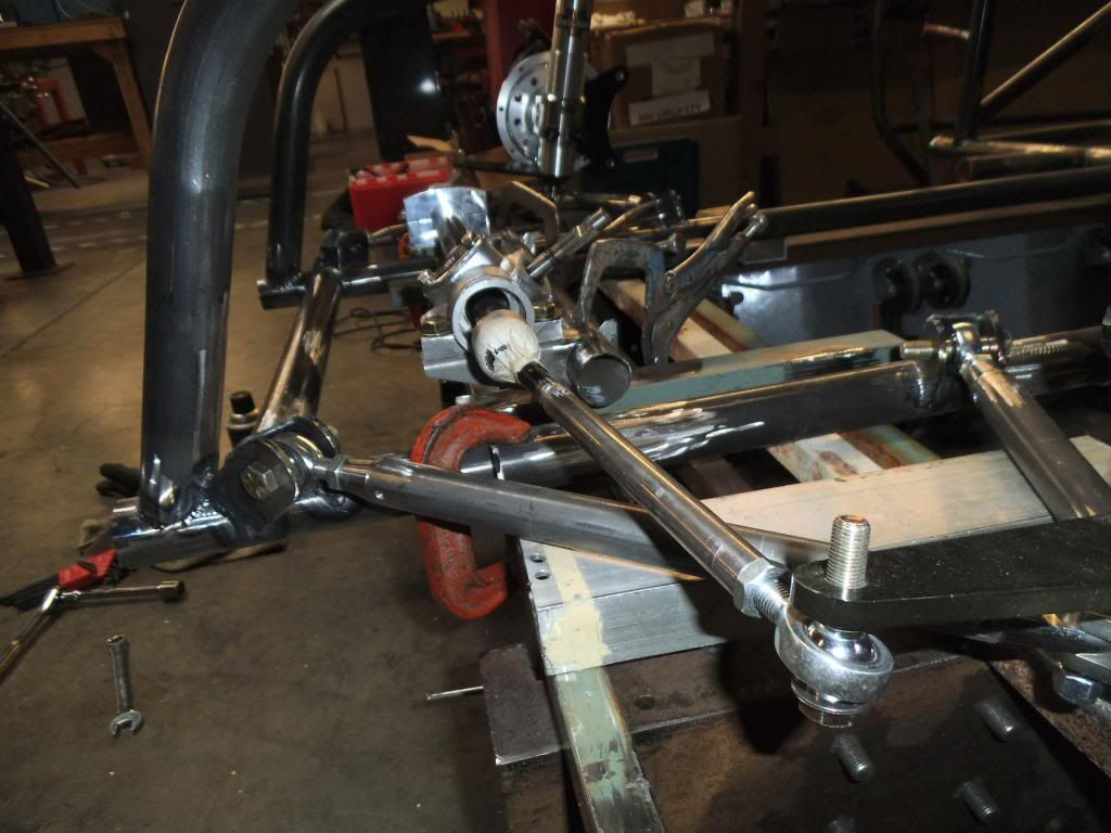
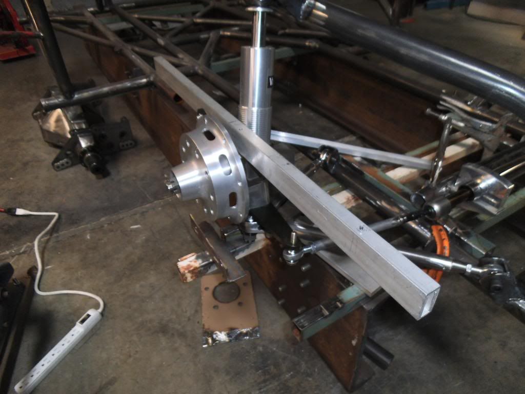
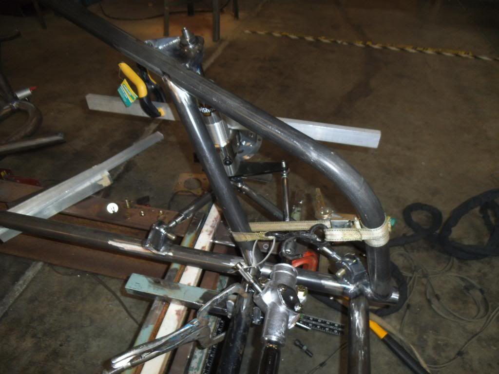
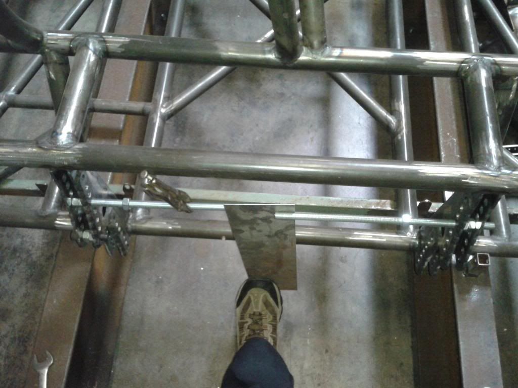
With the mounting points for the right front suspension mostly complete, I moved to the left front and started with a pair of jig support bars precisely placed and tack welded down.

DSCF1925_zps9790c45d.jpg


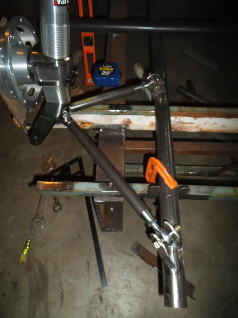
From there I precisely placed and tack welded the "dummy" bars for holding the lower control arm brackets in precise 3D space and angle.

DSCF1927_zps656b704b.jpg


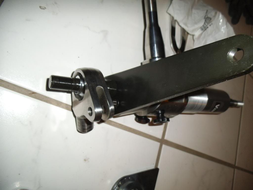
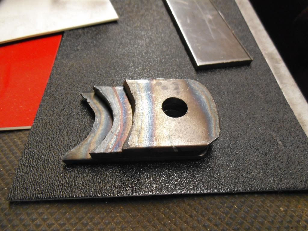
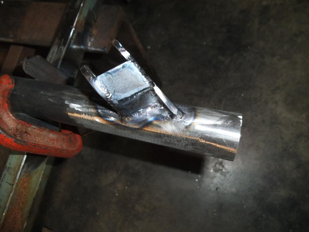
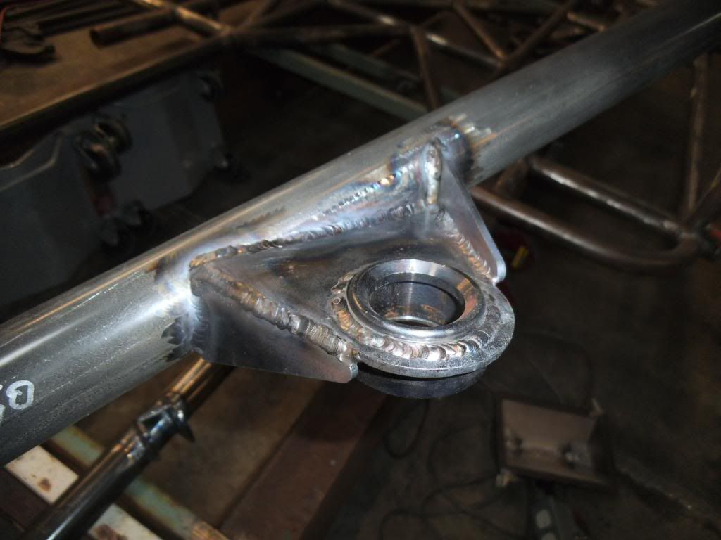
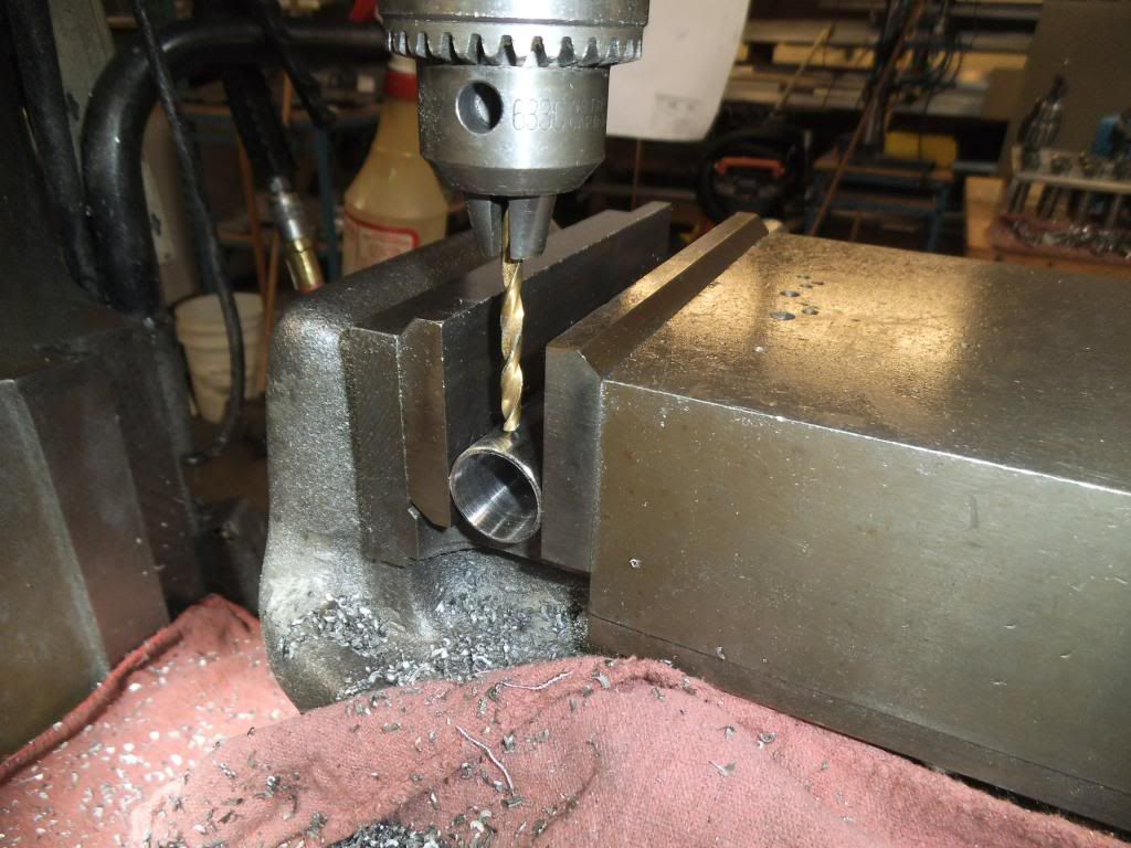
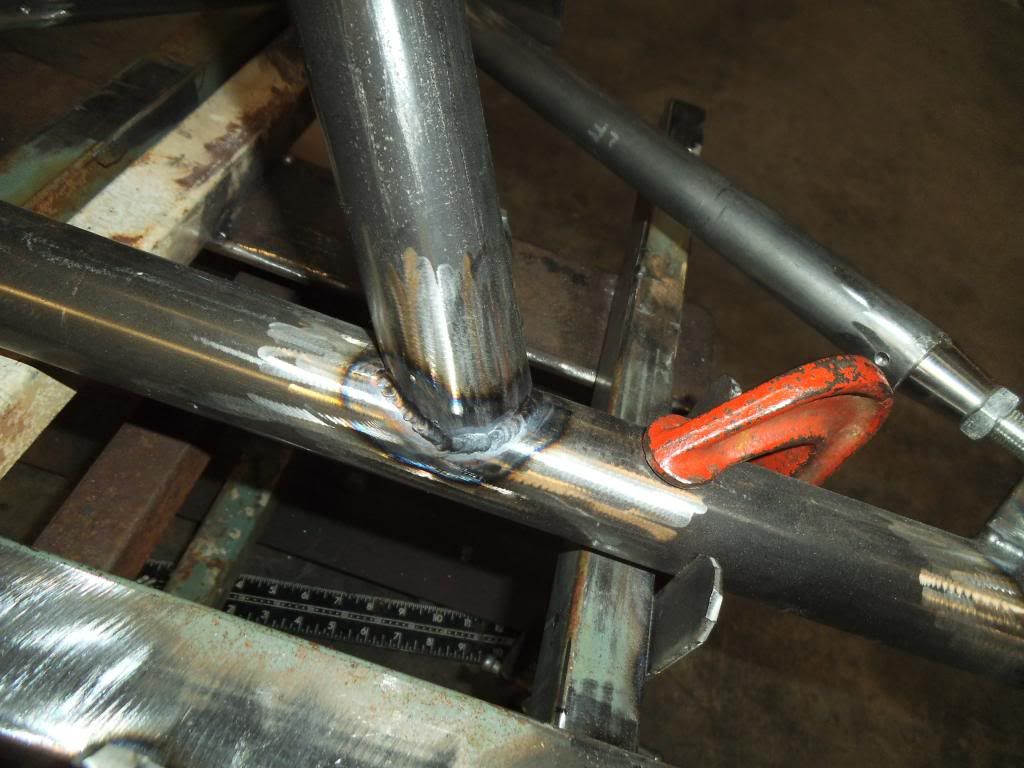
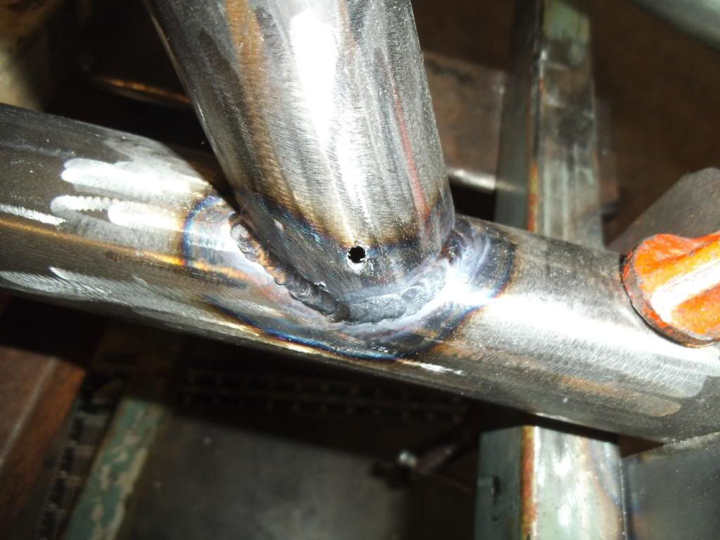
At this point I discovered that making the 1st two of those brackets from my 3D model measurements (back when I was making the ones for the other side) was not such a good idea, with minute differences between the real world and my model.

DSCF1941_zpsc7156db8.jpg


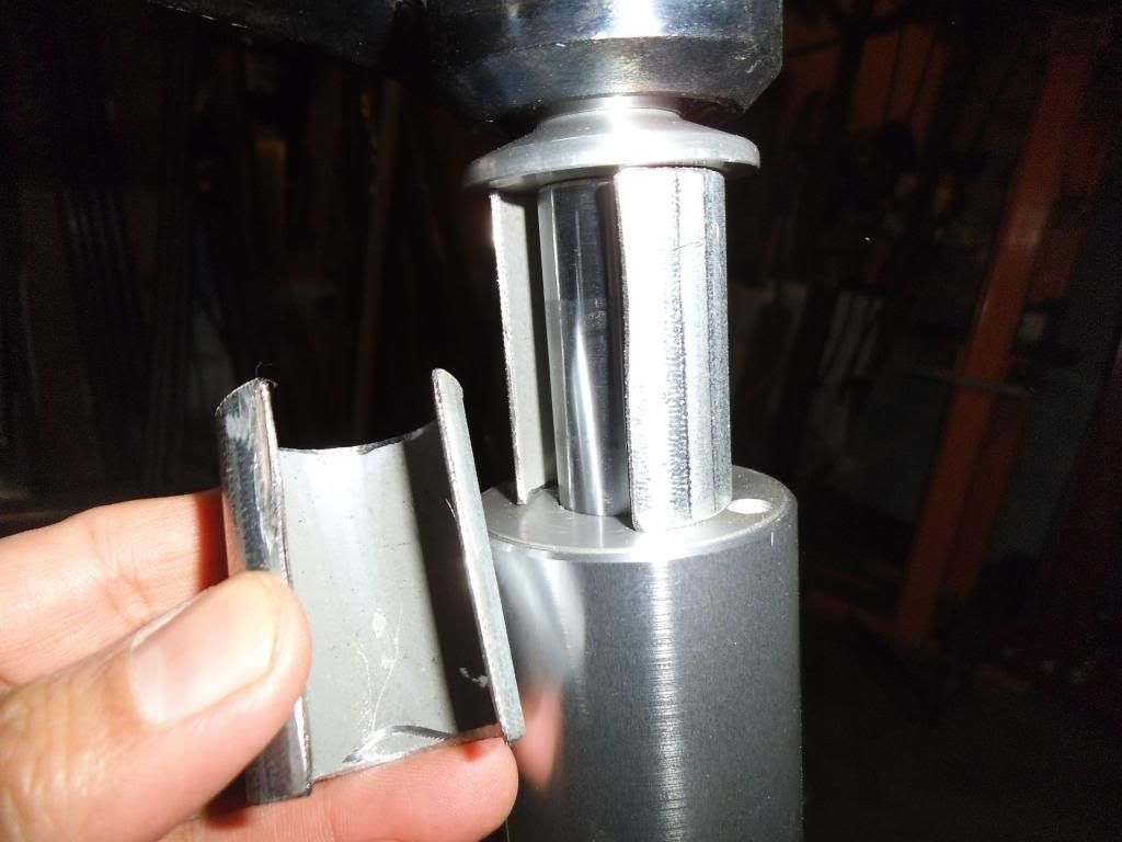
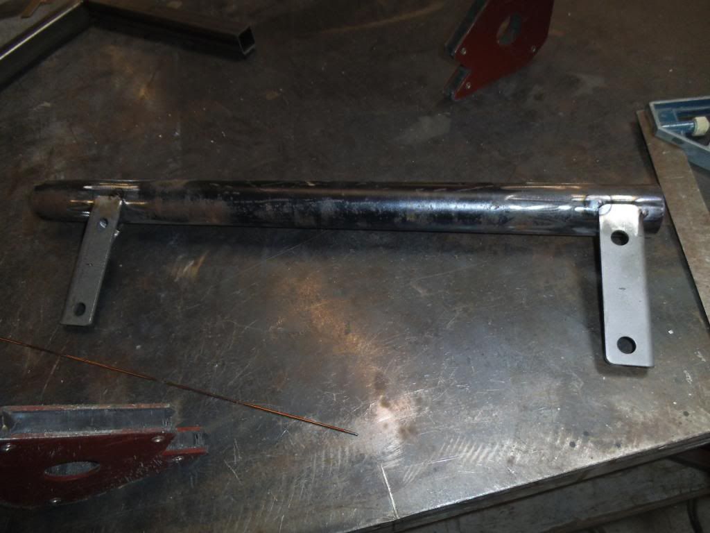
The material for the brackets (like everything else on this chassis) was 4130 CrMo, but in this case it was a strap 3/16" thick a custom width to get the optimal size to get full engagement with the tubes and angles in question. Fortunately when I custom sheared these strips from plate stock I made extra! And since the four pieces are varying lengths, I could replace the longest one and use each piece to replace the next shorter one while leaving me enough length to get a precise zero-gap fit-up.

DSCF1948_zpse71f7f10.jpg


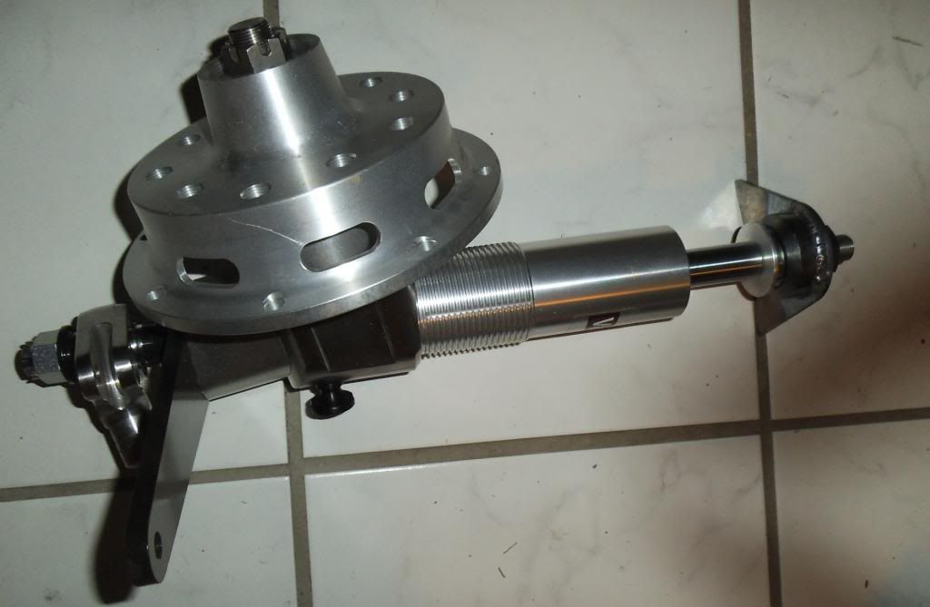
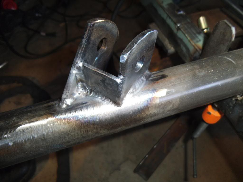
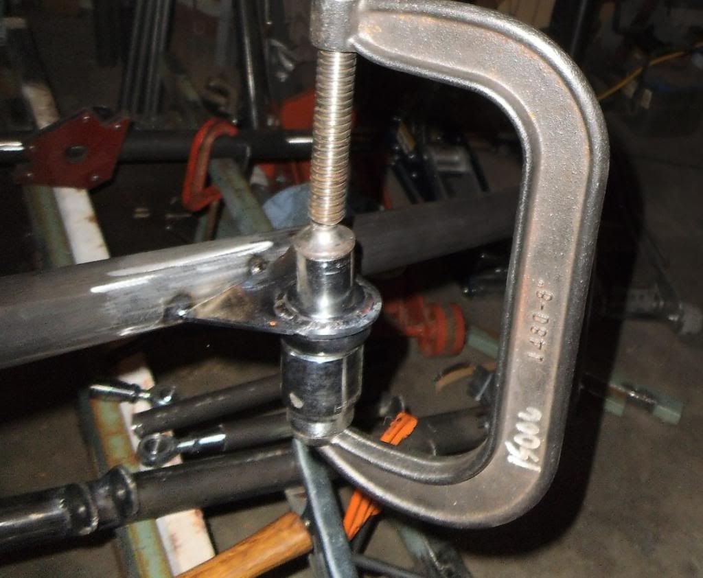
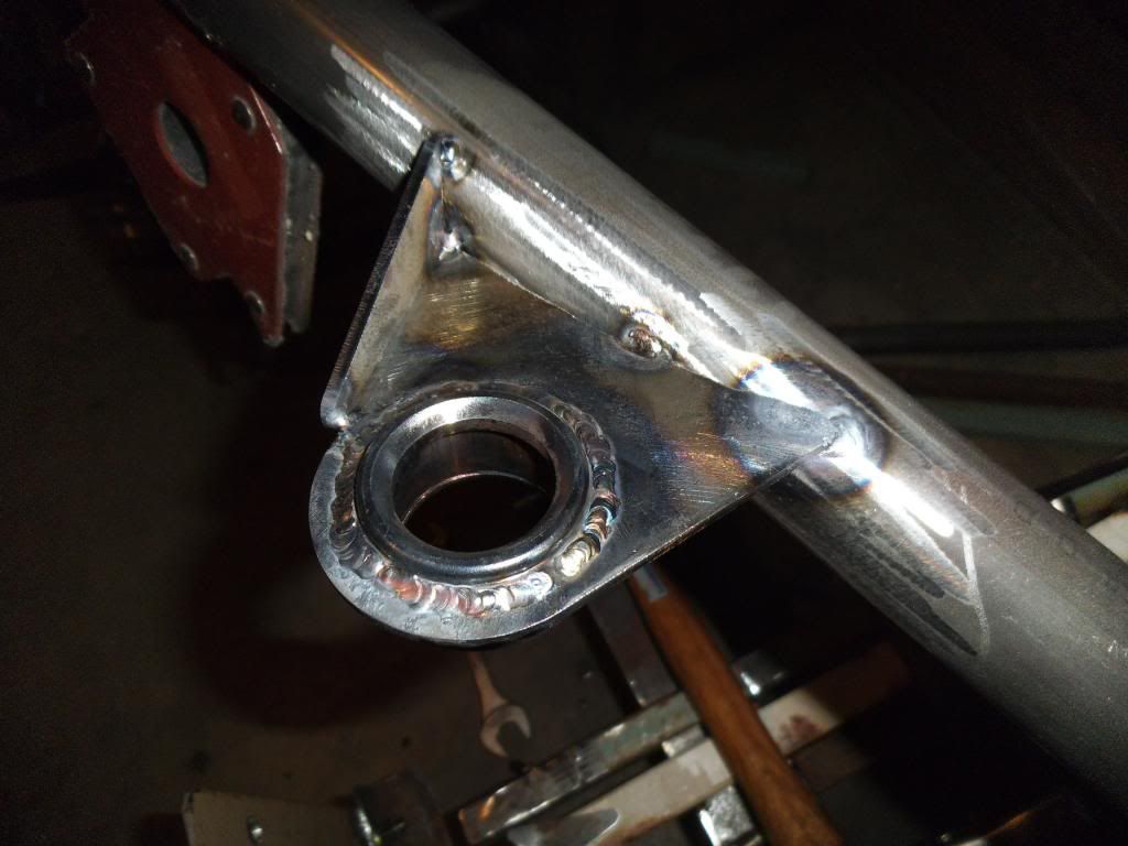
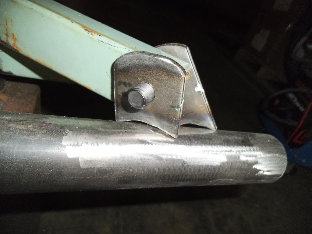
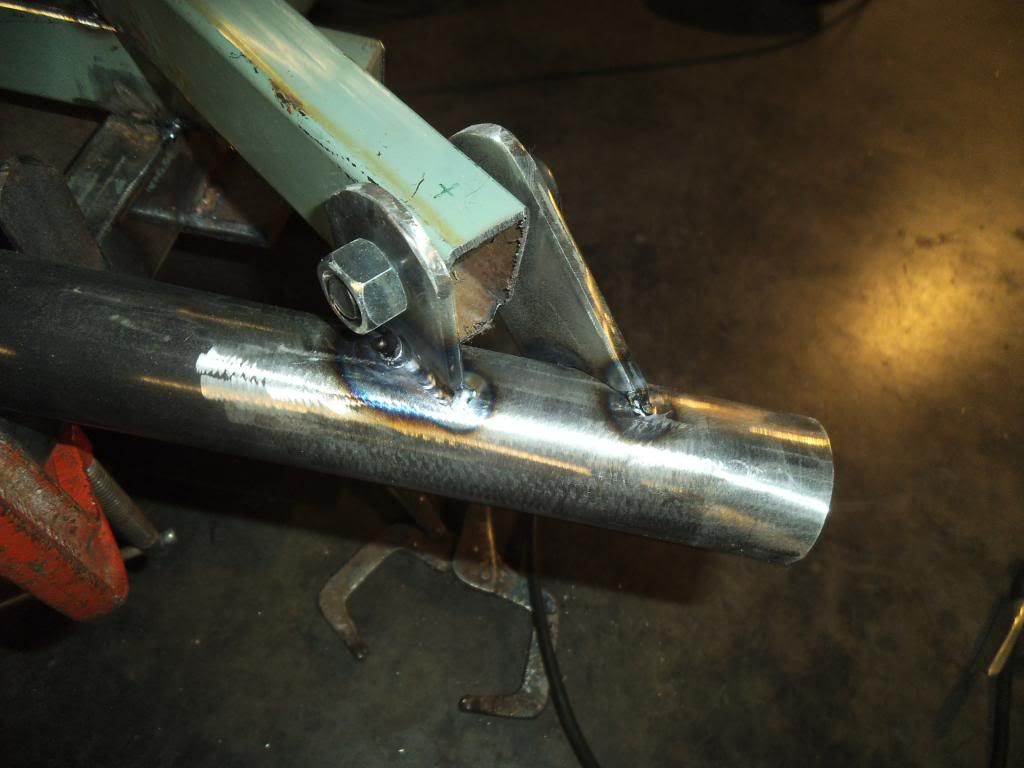
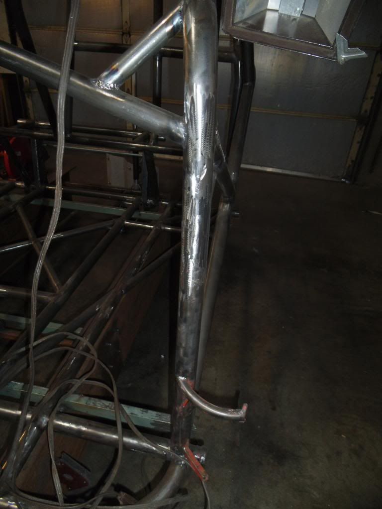
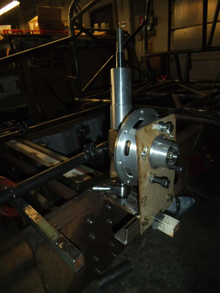
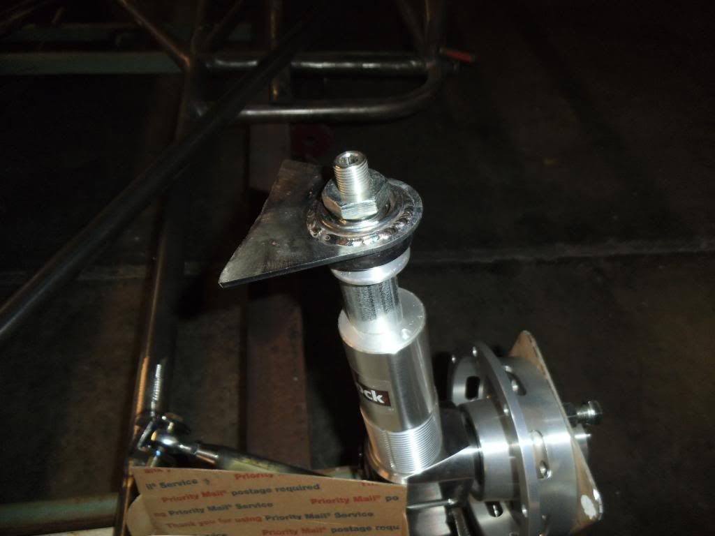
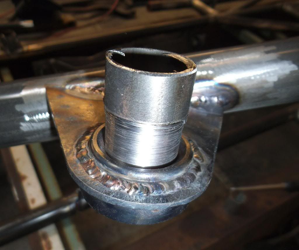
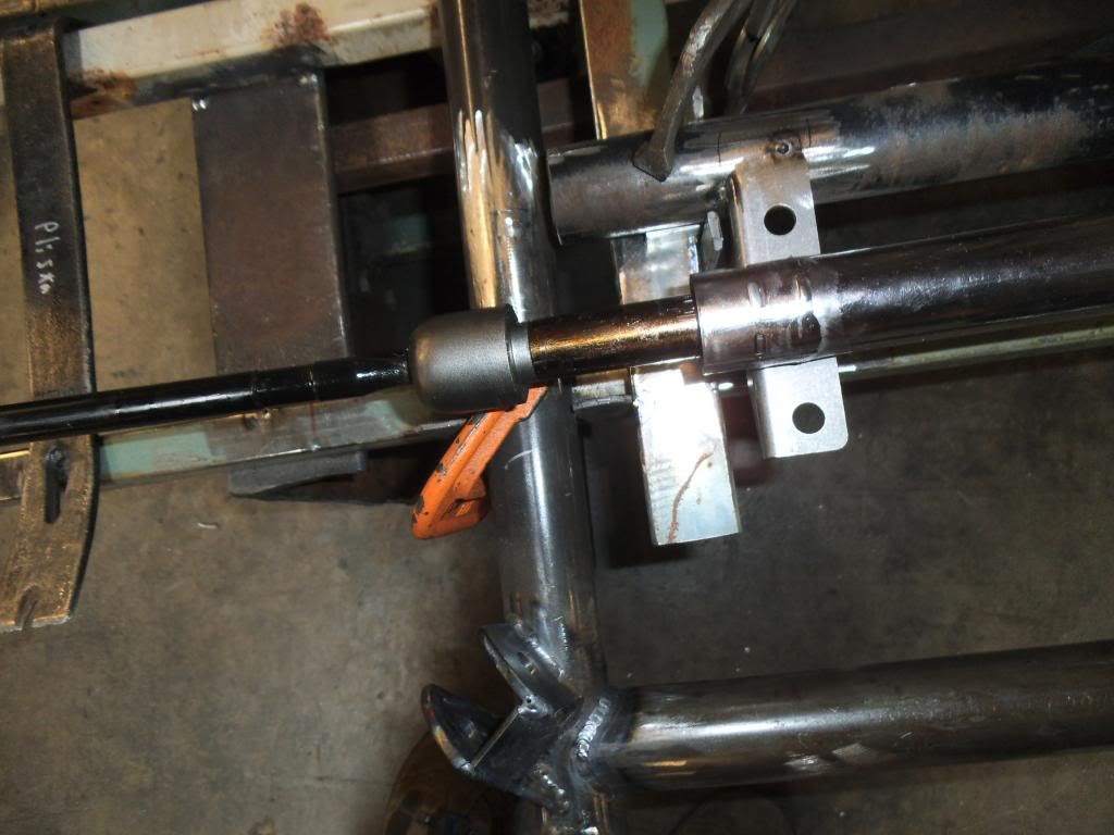
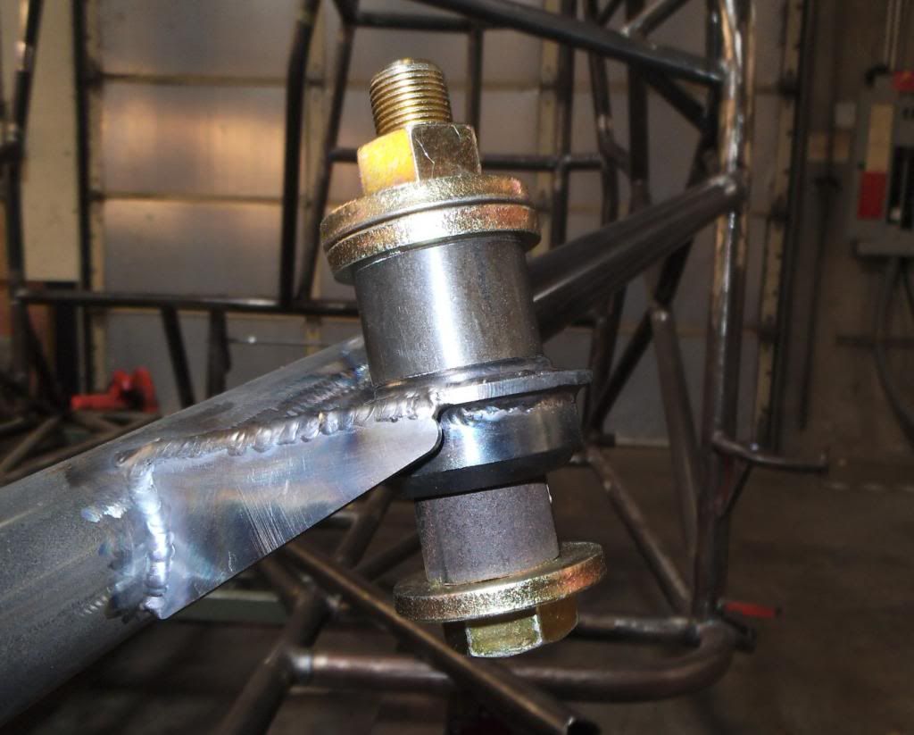
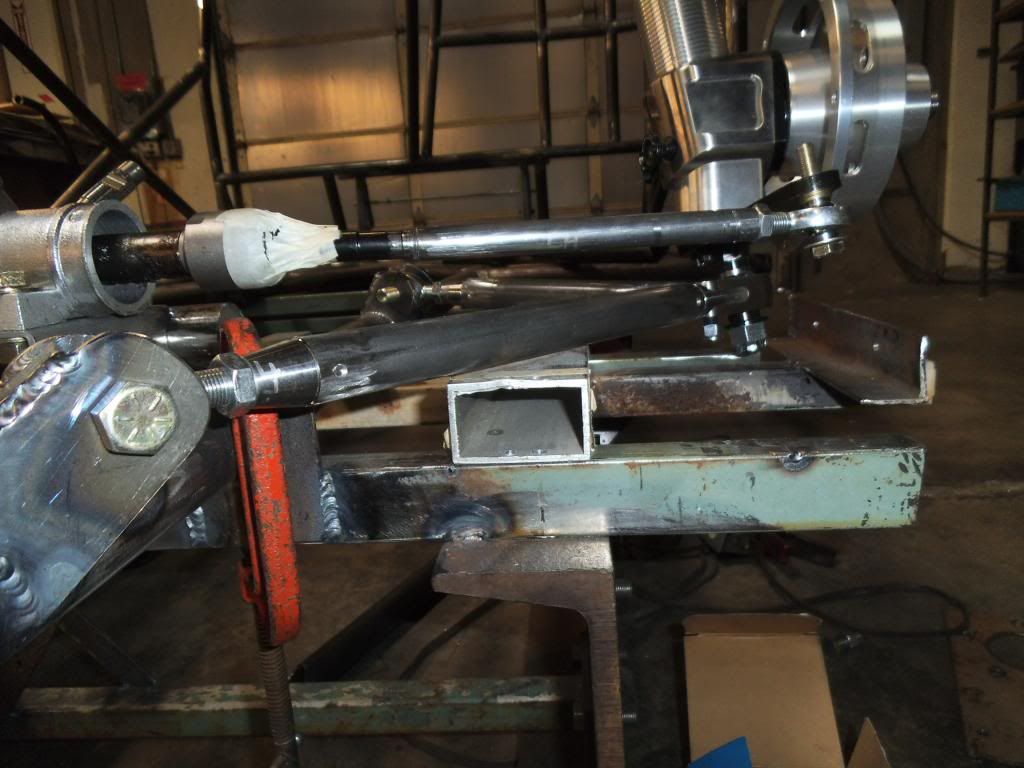
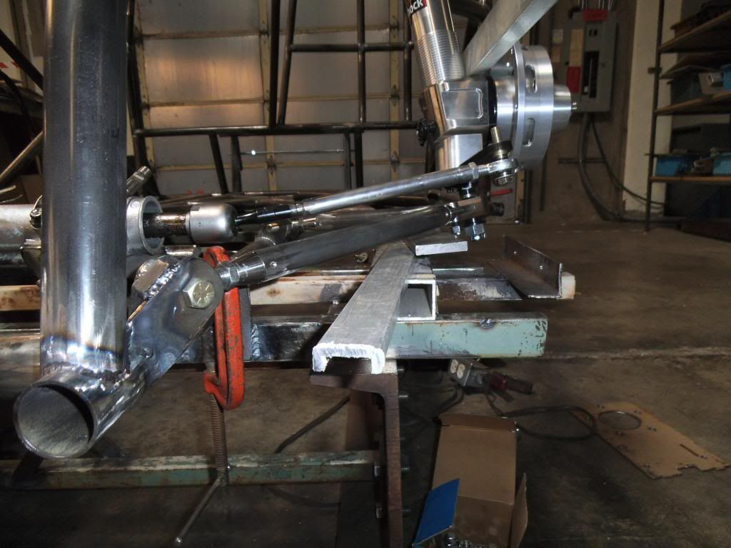
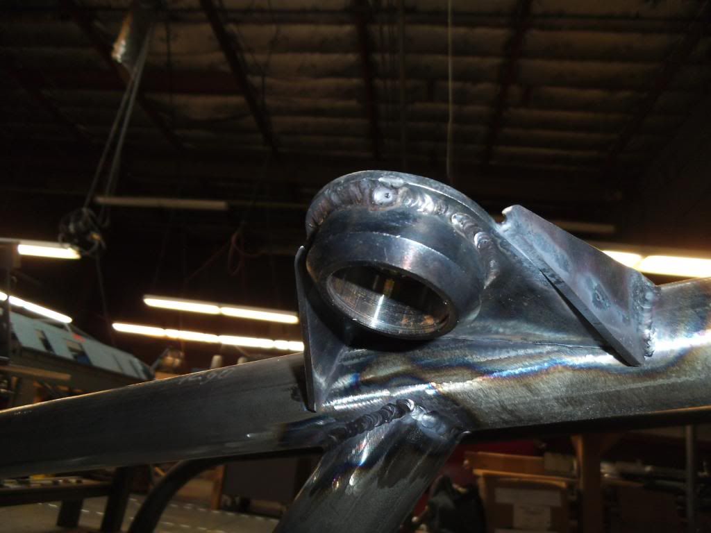
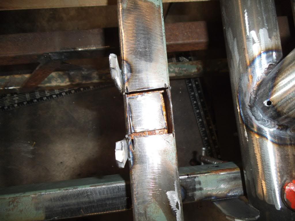
While intermittently fitting up those pieces I also welded the remaining supports on the right front strut upper mount, just welding 3/4" at a time to avoid weld draw.

DSCF1930_zps7d4028c7.jpg


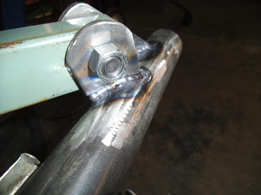
The front outside mount in this picture was the most difficult one to fit with its weird compound angles, but I just went VERY slowly with metal removal until it fit!

DSCF1963_zps61e7c441.jpg


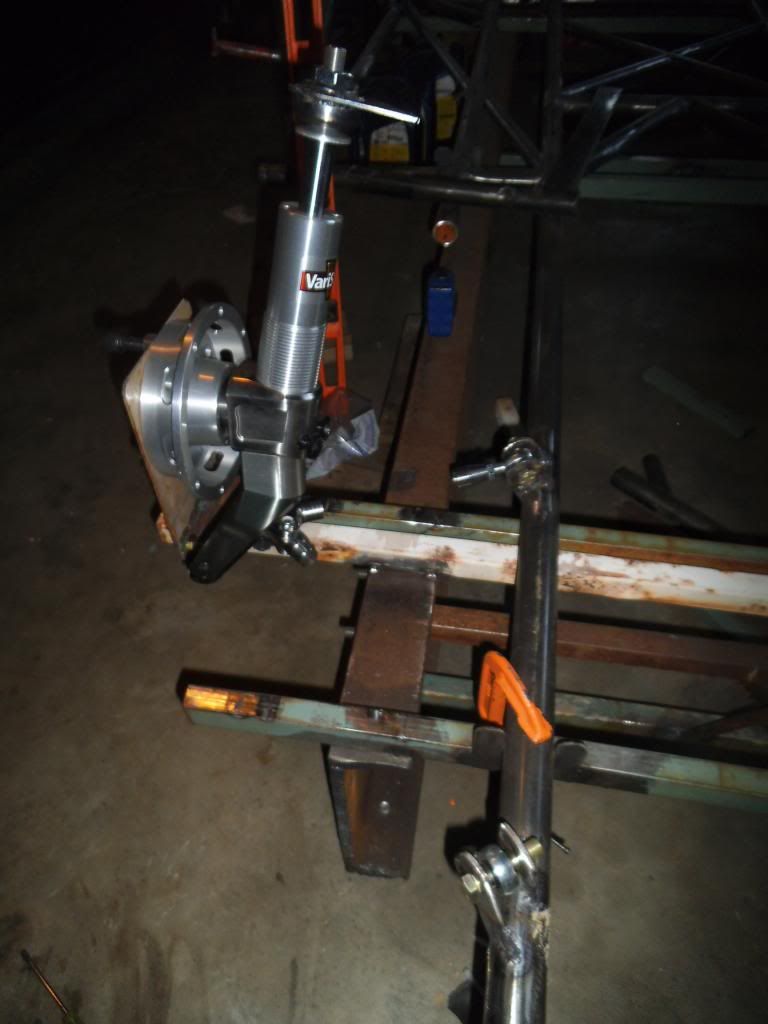
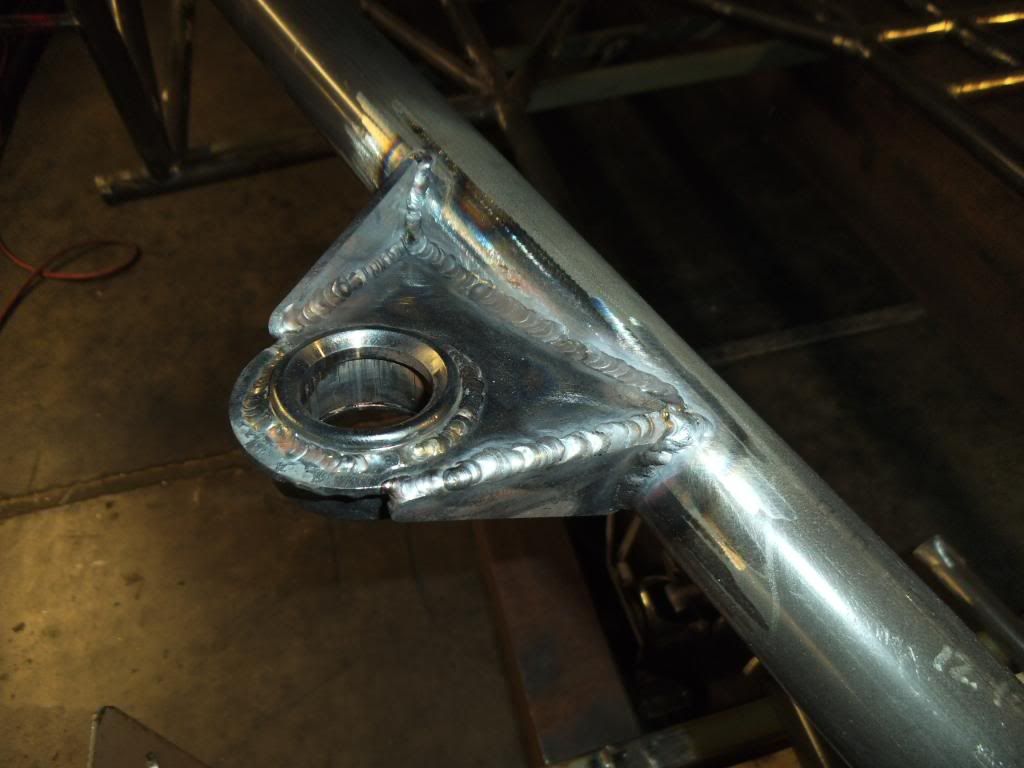
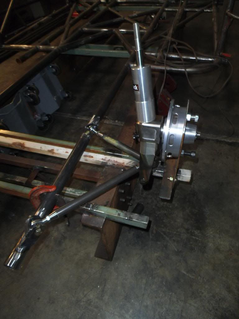
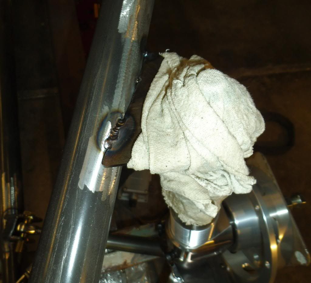
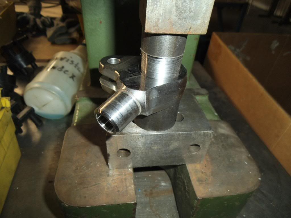
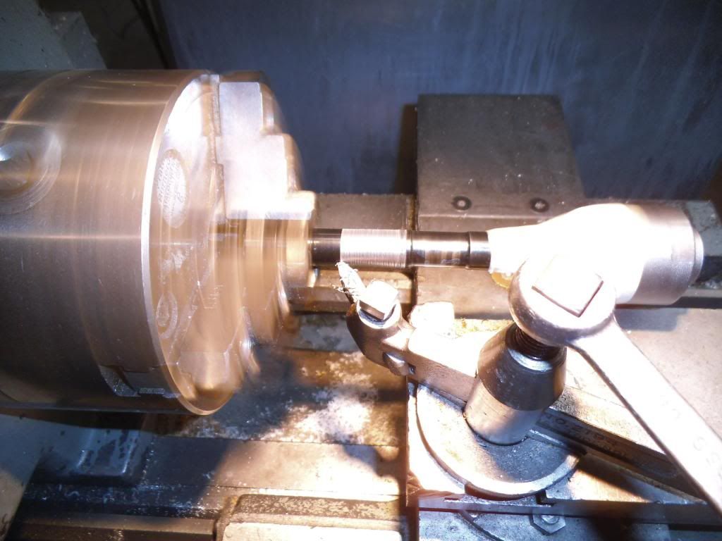
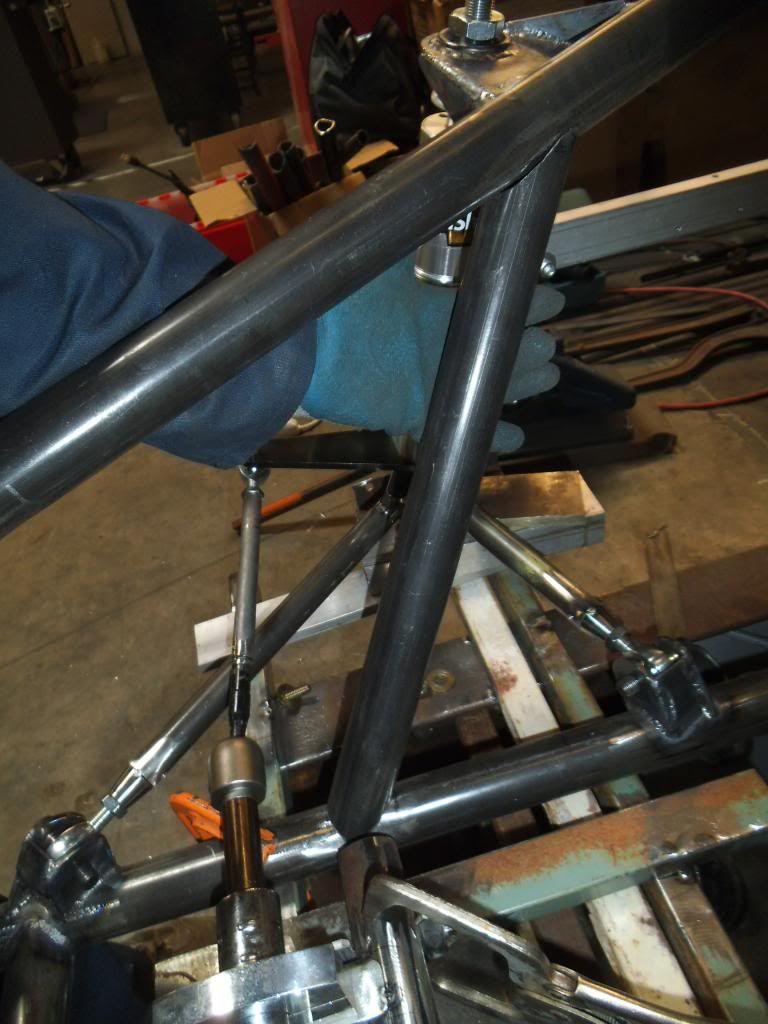
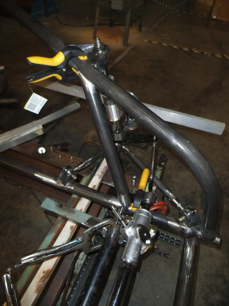
The rears were a little less work since the angles weren't as severe.

DSCF1962_zpsb4018180.jpg


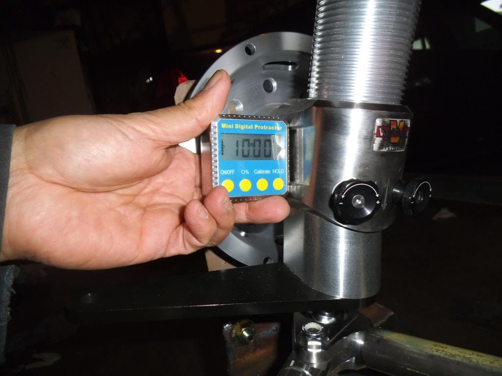
At this point I was ready to start tacking them in place:

DSCF1964_zps9d01a2f9.jpg


Unfortunately it was also time to lose another week on the project, as ISSPRO is displaying at the ConExpo trade show all week in Las Vegas. Thankfully this show is only once every 3 years, but of course it had to fall right as I was starting to make good progress again! I guess I'd better make sure to finish the project before the next ConExpo in 2017!!!
 
Last edited:
Unfortunately it was also time to lose another week on the project, as ISSPRO is displaying at the ConExpo trade show all week in Las Vegas. Thankfully this show is only once every 3 years, but of course it had to fall right as I was starting to make good progress again! I guess I'd better make sure to finish the project before the next ConExpo in 2017!!!


LUCKY! I started with a new company recently so I missed the boat on getting to go to that.

Loving the fab skills!
 
LUCKY! I started with a new company recently so I missed the boat on getting to go to that.

Loving the fab skills!
Thanks!

While I do enjoy the trade shows, I get tired of spending the time away from my daughter and from working on the race truck!
 
Michael, your doing one hell of a job! Especially with work, being a single parent, and trying to find time to work on your project. :clap:

And I can't wait to see it finished.
 
Wish I would have read this earlier this week. I have been at conexpo all week, and unfortunately I am on the 7am flight out tomorrow morning.

I would have stopped by your booth for sure.
 
Yeah, but you like the karaoke!!!
LOL, but they closed down my favorite karaoke bar here (Imperial Palace)! Found a good substitute - Ellis Island Brewery/Casino. Good beer at ludicrously cheap prices (20 oz microbrews for $2 until karaoke starts, $2.50 after that). Unfortunately the song selection isn't as good as some, and it gets pretty smoky as the crowd grows, but it was a lot of fun!
Michael, your doing one hell of a job! Especially with work, being a single parent, and trying to find time to work on your project. :clap:

And I can't wait to see it finished.
Thanks! Juggling all the responsibilities is difficult but fun!
Wish I would have read this earlier this week. I have been at conexpo all week, and unfortunately I am on the 7am flight out tomorrow morning.

I would have stopped by your booth for sure.
Bummer! I was surprised how many diesel friends were here for their "day jobs"!
 
Episode 20:

The ConExpo show was great, except they have the show go through Saturday. At all 4 of these I have worked at, it is completely dead on Saturday. I sure would have rather been back at the shop working on the race truck!!!

Once I was back, next step was to fully weld the left strut control arm tabs (they were tacked in place before I left for the show).
DSCF2061_zpsd095a9d1.jpg


After triple checking that they were positioned correctly, I removed the jig fixtures which had been holding them:
DSCF2062_zps7644bbfc.jpg


DSCF2064_zps32b51458.jpg


At that point I welded in between the brackets, which was time consuming as I swear that puddle would jump up and contaminate the tungsten each dang time I started an arc! I spent waaaay too much time resharpening tungsten at this point!

DSCF2065_zps419e956a.jpg


Next up I added gussets, and finish welded the gussets on the other side.

DSCF2081_zpsbd01833b.jpg


While contemplating whether to sharpen more tungsten or call it a night, I realized that I needed to cut off the top door hinge on this side, to make room for the main strut support bar.

DSCF2085_zps293fd2fd.jpg


At that point I had another interruption in the progress, as it was time for the NHRDA season-opening event in Bakersfield, California. I had really hoped to have this truck done in time to race there, but I wanted to at least go down and support our customers, and hopefully score some points in the Sportsman ET class in my dually. I managed to make it to the quarter-finals before hitting the brakes too hard and losing by 0.01 seconds to my friend Dustin Gullet of ATP Trucks.

That event was the start of Spring Break, and my daughter was spending the whole week at her mom's house. I looked forward to late nights filled with lots of progress, but managed to catch a really bad cold (presumably from one of the dozens of people I talked to in Bakersfield). I suppose I was due, as I had managed to avoid colds & flu for well over a year.

Next step was to add the fixture for holding the front hub in place. This is one of the critical measurements of the chassis, so I checked and adjusted many times to get it perfect. One trick I did was to make a dimple in the plate 180° out from the top bolt hole, but on the bolt circle. I could position by that dimple mark, then make sure it was exactly vertical with the centerline of the top bolt hole.

DSCF2086_zpsed3e00af.jpg


I had pre-drilled pilot holes in the angle that mounted to the jig, then clamped it firmly into place and drilled through both surfaces with a bit that would be a net fit with the 3/8" bolts to hold it together. I wanted zero slop once bolted up. Once I had that all together I assembled the strut and bolted the hub up to the plate.

DSCF2092_zpsf20a5597.jpg


I used the control arm tubes I had already precisely cut for the other side, and adjusted for slight variations with the rod ends.

DSCF2095_zps2d4406d2.jpg


At this point I suddenly realized I was kind of "painting myself into a corner", as I planned to add a front crossmember in this area, and it would be a pain to slide it past the mounts once the main strut support bar was in place. As much as I hated taking a step backwards, I disassembled the precisely positioned lower control arms and lifted the main frame tube out of the jig, so it could be flexed over to install the crossmember.

DSCF2098_zps0a35ccbe.jpg


With that done I reassembled and adjusted the control arms, then added the upper strut mount:

DSCF2103_zps395bceb3.jpg


Fitting the strut support tube was a pain, both having to be notched to clear the control arm mount, and being positioned in 3 dimensions at 3 different points (lower front, upper rear, and center with the strut upper mount).

DSCF2106_zps65a9b403.jpg


After what seemed like a thousand test fits and adjustments I finally had it ready to tack in place. I used a clamp to help the magnetic mounts that I usually use to help hold tubes in place, so I could be sure it didn't slip wtih the repeated test fits:

DSCF2112_zps71b17108.jpg


While tacking the upper strut mount I remembered how much hassle I had with the other side moving around after I removed the strut and bearing from it, as the instructions were very clear to only do the smallest of tack welds before removal or risk damaging the bearing & strut. I decided to try a slightly different approach, and kept a soaking wet rag over those parts so I could put a much more robust set of tack welds:

DSCF2113_zps16e6b34a.jpg


When it was time to remove the bearing, I realized that the socket I used to press it out before was pressing on the bearing spherical portion rather than the outside race, so I needed a very precisely sized tube to do it instead. Fortunately there is a big metal lathe at ISSPRO, so it was quick work to turn down a piece and use it to press the bearing out and finish the tack welding:

DSCF2124_zps82833df8.jpg


Another trick I learned was to use clamps near the weld when welding around tubes otherwise "out in space", to give my hand a steady spot to rest on while welding. It made me much less likely to contaminate my tungsten, which was a welcome change since I had spent so much time sharpening it so far! Now if I could just get my daughter to sharpen my tungsten for me while I keep working...
 
Episode 21

I swear there is always something that keeps me from spending time on this build. In this case I lost a few days to clearing up a case of ID theft! I went to file my taxes and found out that someone had already filed a fraudulent return using my information. It turns out that a large percentage of people who volunteer for Catholic schools in our part of the country had this happen, apparently by someone in the company they used for the legally required background checks. Too bad they couldn't have paid the tax bill I actually had due!

After filing tons of reports, I went back to the chassis and quadruple checked positions on everything, thenI finish-welded the left side strut support bar:

DSCF2129_zps2d292581.jpg


Next up I welded the left upper strut mount with its gussets:

DSCF2126_zps64ae47a7.jpg


The plans from Chassisworks called for the crossmember for mounting the steering rack to be about 1.5" higher than the bottom main chassis tubes, so I couldn't just tie between those tubes like the front crossmember I previously installed.

My plan was to add a couple of angled braces from the main frame rails to the strut support tubes, both to reinforce the strut mounts, and to give me a spot to tie the steering crossmember to. Unfortunately the strut tube and the main frame rail are at a compound angle to one another, so it is VERY difficult to fit the tube to both sides. I managed to notch the first tube a little too far, and had to start over. Good thing I have some extra tubing!

After I test fit that tube I suddenly realized that even a slight change in the position of the steering crossmember would change the length & angles on this tube! I decided to fixture up the position of the steering crossmember to be sure.

DSCF2131_zps268d25cd.jpg


As I was starting to test fit the steering crossmember I realized that since the bottom of it was just below the top of the main frame rails, it would require a double notch on each side.

DSCF2132_zps8a98b83b.jpg


Since all of those dimensions and angles would change with a slight change in position, I used a shorter piece to make a temporary steering crossmember, so I could make sure the steering rack position was perfect.

DSCF2133_zps93efd6e4.jpg


I clamped it into place on my previously added jig fixture:

DSCF2134_zpsb5a01f9e.jpg


At this point I was relieved that I had done all of this as a mock-up, as the dimensions for the steering mount placed one side too far outboard, where the clamp would hit a bulge in the rack that was there to hold the boot:

DSCF2138_zps97e01a3c.jpg


I remember the Chassisworks tech guy telling me that they don't make the steering racks themselves, and it has been getting harder and harder to find a place to build them. It appears their current supplier has the dimensions a little off from the original Pinto application that used these.

Now for a little boring sidebar on steering geometry:
The most critical part of all of this is eliminating what is known as "bump steer", you need to make sure the front tires do NOT change direction even the slightest bit as the suspension goes through its full articulation. In order to accomplish this the pivot point on the steering needs to be perfectly aligned with the pivot point on the lower control arms, and the height such that the steering tie rods are parallel to the lower control arms.

I decided to pull both boots so I could see for sure where the pivot points were. Sure enough, even with the steering rack centered as far as its travel, I needed to move the whole thing 0.5" to the side (in addition to moving the clamp mount as mentioned above).

DSCF2139_zps2322a5c8.jpg


At this point I really needed the control arm & strut assemblies together so I could check the aforementioned parallel requirement. I pressed the bearings out of the lower control arm ends:

DSCF2144_zps2646291e.jpg


The tubes needed to be drilled for rosette welds:

DSCF2145_zps227381ac.jpg


I just tack welded them together for now, in case I need some adjustment in length. While there is adjustment in the rod ends, I want to start out with them right in the middle of their adjustment!

DSCF2149_zps98eb17a4.jpg


As I went to assemble everything, I pressed the spherical bearings back into the A-arms without too much effort, but when I went to press the bearings into the upper strut mounts I found that the weld distortion made it so hard that I was bending the biggest C-clamp I had! This was even after freezing the bearings! I was prepared to heat up the sockets as well, but decided to come up with something different for pressing the bearings in. I ended up using some specific cut sections of tubing with a 3/4" fine thread grade 8 bolt, which had the secondary effect of forcing everything into alignment as it pressed it together. No need for heat as this pulled the bearing right into place.

DSCF2154_zpse5ba1f57.jpg


I used shims between the control arm and the jig to hold the strut assemblies exactly at ride height, then measured off where the updated tie rod tubes and the original tie rod shafts needed to be cut in order to weld them together.

DSCF2158_zpsf50ec285.jpg


I learned that this was another area where the reproduction Pinto rack was different than the factory ones. This one used a MUCH larger diameter tie rod shaft than the originals, and the originals normally fit into the tubes I am supposed to weld them to.

I made the cuts, counterbored the tubes (they were counterbored for their ends, but needed to be rebored since I was cutting them so short), then used the lathe to cut down the tie rod shaft diameter to where it would fit:

DSCF2166_zpsdb745a4f.jpg


DSCF2167_zps992a8dad.jpg


Now I should be able to tack everything together and verify that the steering geometry holds up throughout the suspension travel.
 
Episode 22:

To start out, I wanted to give a shout-out to Hughes Performance. Early in this build I had decided to use their XP-5 Lockup Pro Mod Powerglide transmission, which was the most expensive of the options I was considering, but was rapidly achieving a track record of being the most durable option out there. When I bought it, they told me to keep in touch with them since this was a new design for them, and they may have updates to the design periodically. My cynical side was thinking "sure, come up with more ways to charge me more money". As I was getting closer to having this truck completed I decided to contact them to see what updates were available (and whether I could afford them). To my surprise there was no charge, and they took care of everything. One significant change they made was to switch to a larger steel bellhousing, which allows the use of larger torque converters. This has been necessary to hold the increased torque of compound-turbo engines (their earliest test units had used parallel charger arrangements).

DSCF2201_zps13365322.jpg


Back to the chassis and the steering. I drilled the tie rod extension/adapter rods for rosette welds, then tack welded the tie rods together, assembled them back to the steering rack, clamped the rack into my jig location, then assembled the rest of the steering:

DSCF2173_zps0c4583d5.jpg


With the suggested position from the instructions, the tie rods appeared to be parallel to the control arms:

DSCF2177_zpsed7f311d.jpg


For measuring toe-in, I bolted some aluminum tubing to the caliper brackets (which stay parallel to the rotors). The tubing was much longer than the diameter of the wheels (where toe-in is normally measured), which would magnify any toe-in problems. I can scale the toe-in changes back to the dimensions of the wheels for comparison with known standards, but I wanted a very precise measurement as I adjusted things to minimize the toe-in changes.

DSCF2195_zps0f415b5c.jpg


Checking the suspension at various heights, I found that toe-in changed an unacceptable 0.26" through the full travel.

Consulting a couple of chassis building books, they recommended dropping the rack position with such a result. I dropped it 0.445", then reassembled and remeasured. Visually the tie rods looked almost too low, but I verified that they did not come close to contacting the control arms at any position or suspension articulation.

DSCF2202_zps4363c4dd.jpg


The result was a total toe-in change of 0.036" (well below the 0.060" that the books recommend as a target).

At that point I went to fit up the angled braces with the revised position of the rack crossmember. Remember when I mentioned trimming one too short before? With the repositioning of things it ended up almost the perfect length, just needing some minor trimming.

DSCF2204_zps9c7f1226.jpg


Remember that I had cut a longer one and began fitting it? It turns out there was enough material to change the angle at the top to its mirror image, and use it for the other side!

DSCF2205_zpsbabcf5c8.jpg


I guess I was too excited from all of this reusing of parts, when I clamped the 1st brace into place and tack welded it, I tacked it on the outside, such that the weld draw of the tack weld started pulling it away from the mating tube on the other end.

DSCF2206_zps4bc132ae.jpg


This required using my good old friend the ratchet strap to hold it in place to weld the other side! After that I remembered to tack on the side where the weld draw will help hold the bar in place...

I welded around on the inside of the tubes at the top, but avoided the outside until I removed the spherical bushings to keep from damaging them with heat.

DSCF2209_zps15641df7.jpg


With no such bushings close to the bottom of the braces I was free to weld them all the way around, but still only welded about an inch at a time to prevent excessive weld draw.

DSCF2210_zps7322e3c1.jpg


As I was doing that I suddenly realized that I had forgotten to drill vent holes to allow the gases to expand into the adjoining tubes! Fortunately I would have the crossmember covering the lower end of these braces, so I was able to sneak a hole in down near the end, and drill all the way through to the tube underneath so the gases can still flow when I weld in the crossmember.

DSCF2212_zps892d67e9.jpg


With the holes in place I was able to fully weld around the tubes (after removing the struts and the spherical bearings to protect them from heat damage).

DSCF2236_zpscc9a93a1.jpg


While those welds were cooling as I did the aforementioned skip welding around the tubes, I decided to try removing the threaded rods I had used to brace the 4-link brackets while I welded them into place. This turned into a classic case of painting myself into a corner! I had sorted the nuts to find ones with the exact width (with two stacked together) for the inside dimensions of the 4-link brackets, then carefully threaded them together when the brackets were still separate pieces. This worked great for holding everything steady while fitting and welding, but now that they were one piece it provided a bit of a challenge!

The first one I had done a while ago, and it took waaay too long. Literally it was like working a stout locknut (that took probably 80 ft-lbs of torque) for about 3' of threads, where you had to turn one pair of nuts one flat, then the other pair one flat, over and over a few thousand times. This time I decided to cut the rod in half, figuring I could then just thread it out the short way (maybe 3" of threads). I had to use a piece of sheet metal to let the ends at the cut pass each other while I did the 1st side.

2014-05-19181512_zpsac98b9ba.jpg


This actually worked pretty well, but of course it still ended up a mess as I was trying to do the remaining half, one of the nuts stripped. I had maybe 3/4" to go, but it will just get cut out with the angle grinder now. In retrospect, I probably wasted $50 of time saving $10 worth of threaded rod!

While doing this "outside the box" thinking I realized that I could always move the rack mounts slightly lower and use shims to bring it to the optimal height. However the position was already against the top of the jig crossmembers I had placed for positioning the rack crossmember. Who says I can't modify those crossmembers? I trimmed out the top surface and ground the edges down to a specific height, to allow a little more adjustability in the rack crossmember position.

DSCF2231_zps3b039857.jpg


As I do the final rack crossmember mounting I will see if I can find a spot that yields less than the 0.036" of bump steer.
 
Back
Top