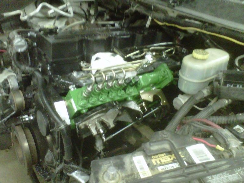
blu_by_u's P-pump swap

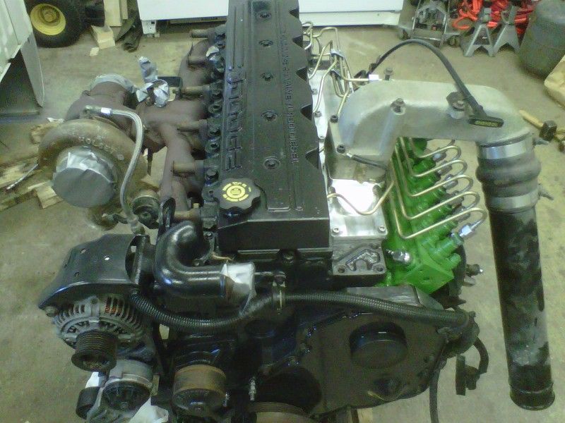
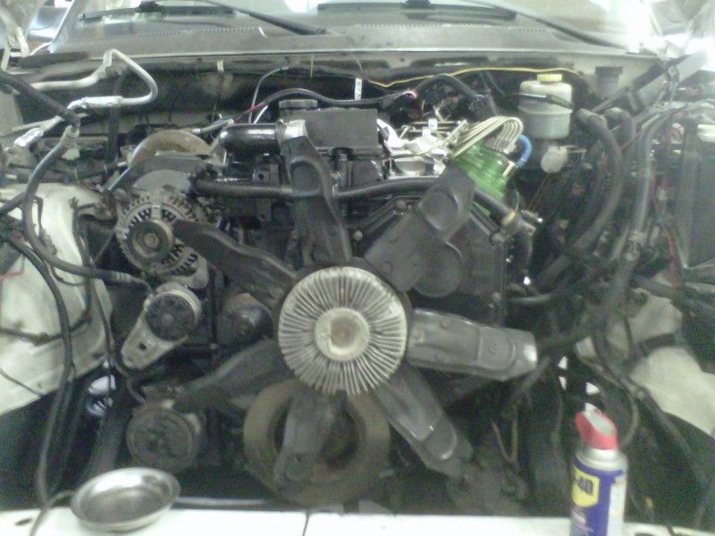
Progress has been slow. My drive to work is roughly 40-45 minutes so when I have been getting off work after 5pm, it's 6pm by the time I get home, then supper, spend a little bit of time with the family, etc.

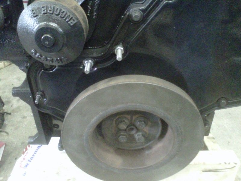
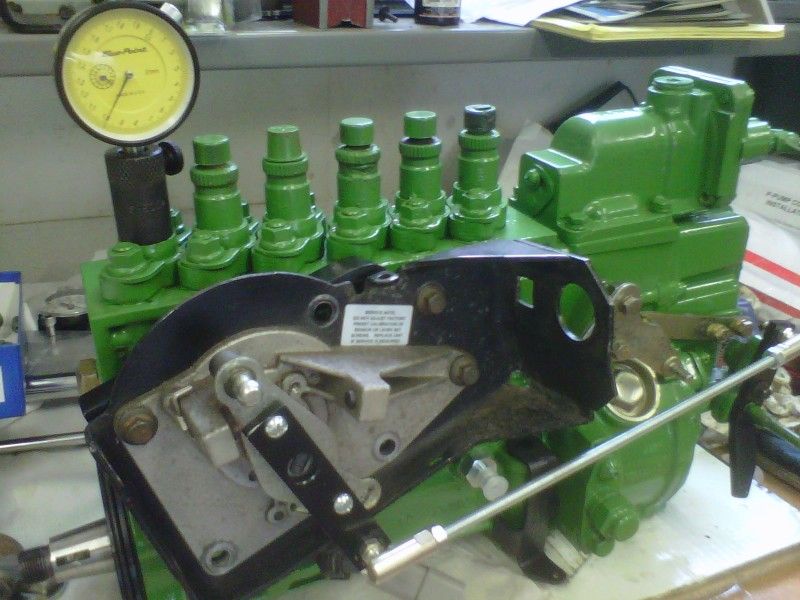
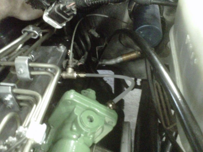
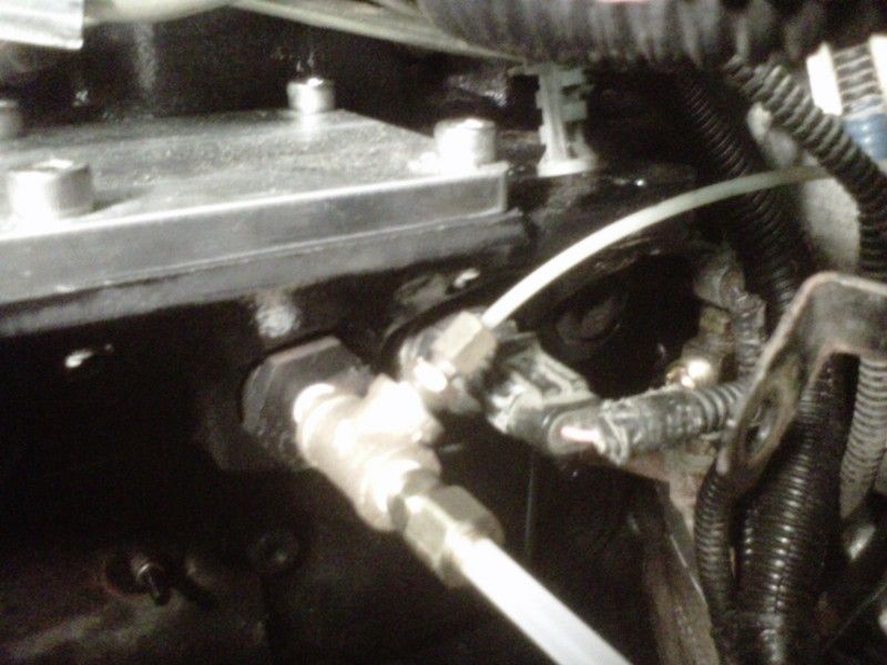
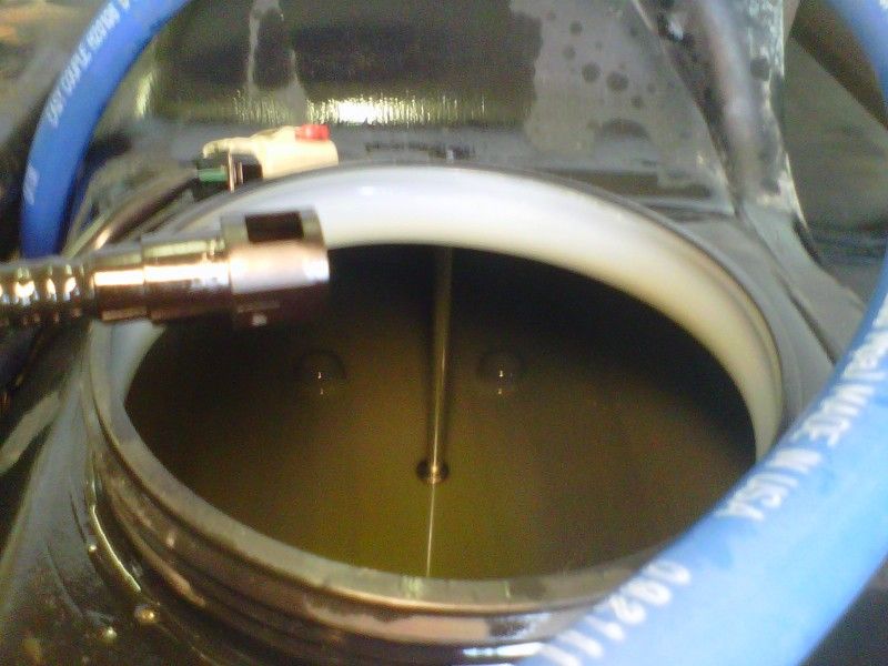
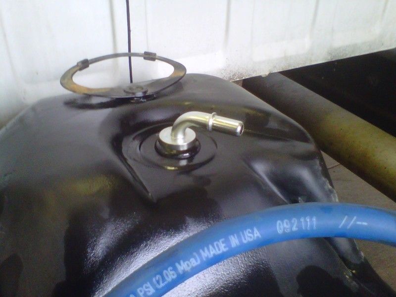
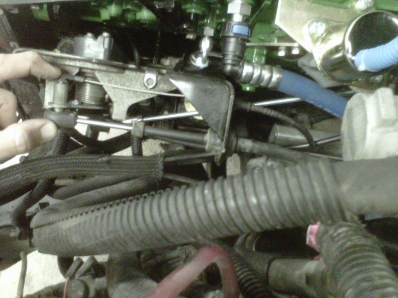
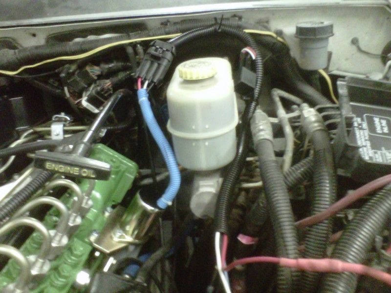
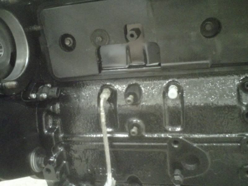
I wanted to get the pump ready to install for good on the engine so I did a little prep work. Here I am removing an oil plug to make room for the pump oil line fitting. The instructions said to use the fitting right behind the factory oil line to the aux drive.
IMG-20120718-00386.jpg


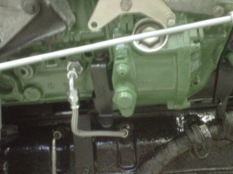
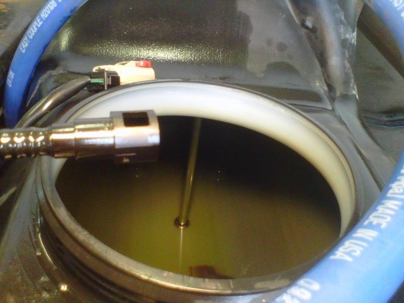
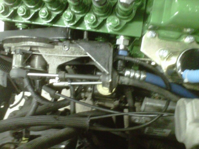
Here is the fitting in the block.
IMG-20120718-00387.jpg


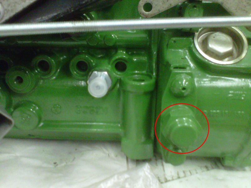
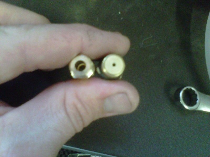
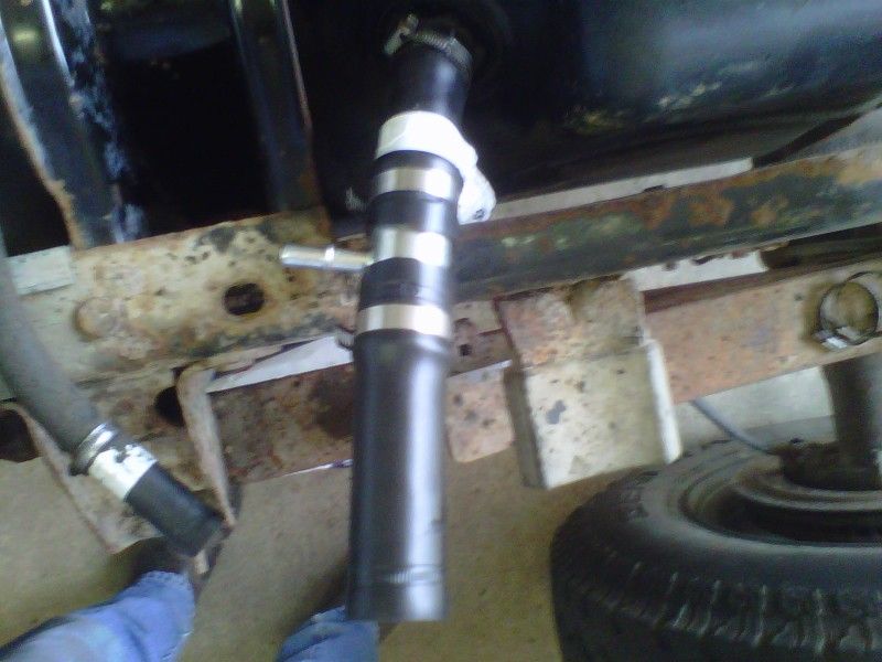
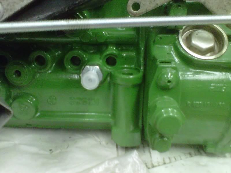
This is the restricted fitting in the pump.
IMG-20120718-00385.jpg


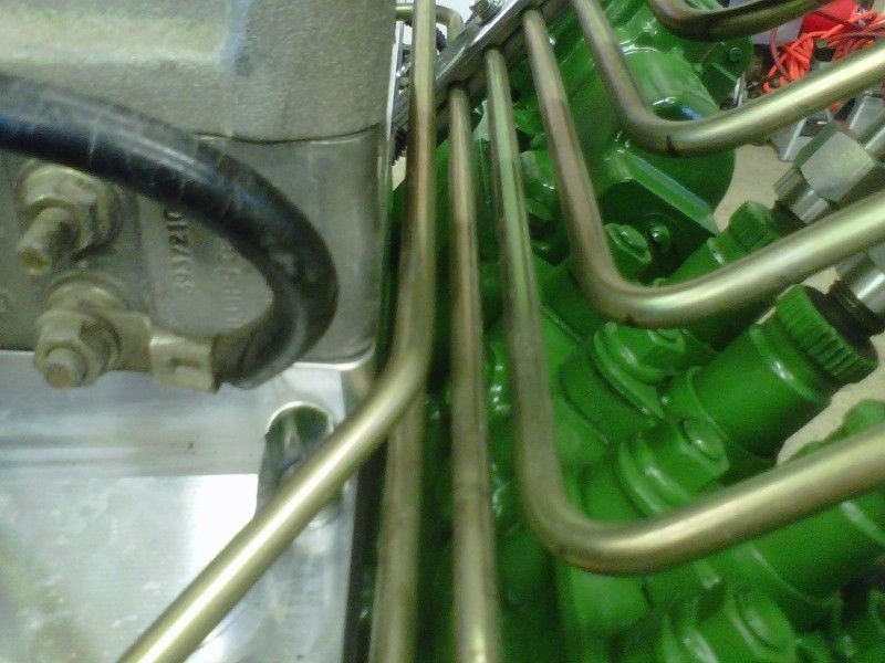
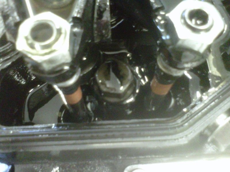
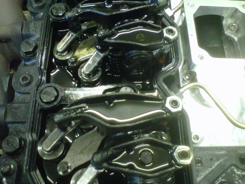
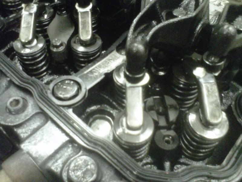
Next I moved on to pulling number one injector so that I could get a better idea of when the crank is at top dead center (TDC) for setting the valves. Started by removing the hold-down capscrew furthest away from the rocker levers. Then the injector hold-down slides right out (you'll see that the other hole is a slot).
IMG-20120716-00367.jpg


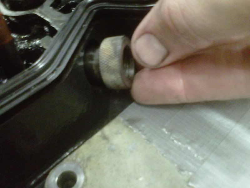
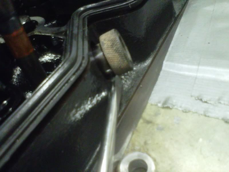
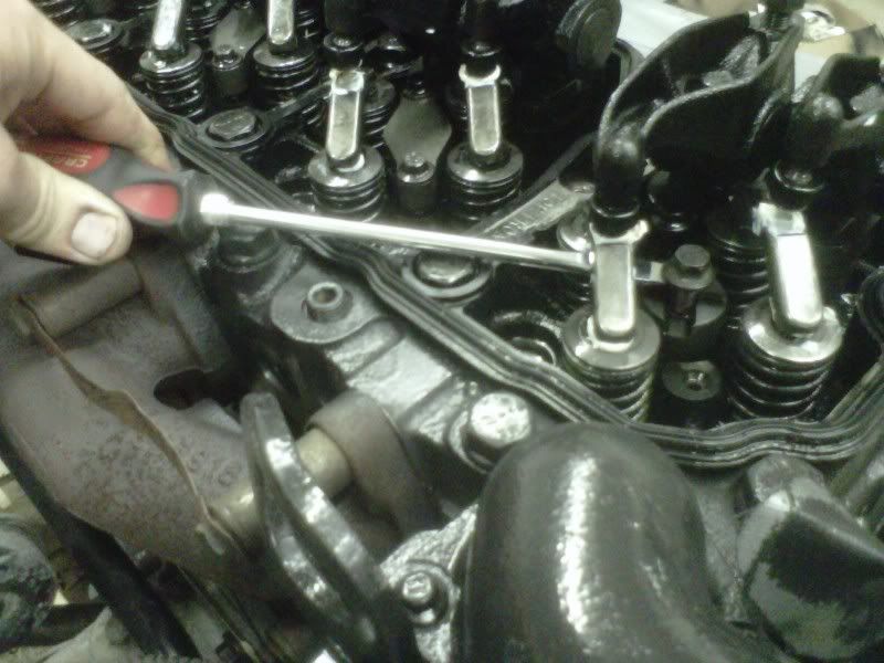
Next I thread on the cross-over tube removal tool on.
IMG-20120716-00368.jpg


Then I use a decent sized straight screwdriver to gently pry the tube out. Make sure that you pry it out as straight as possible to reduce the risk of damaging the O-rings on the tubes.

It's not a bad idea to pull the tubes first so that you don't forget. You 'can' forget to pull them, then damage them when you pull the injector out anyway!
IMG-20120716-00371.jpg


To help get the injector out, I always use one of the shorter bolts that were used to clamp the injection lines down on the intake manifold. I simply thread it into the top of the injector body.
IMG-20120716-00372.jpg


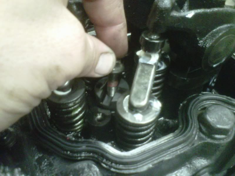
Then I take a decent sized straight screwdriver and use a headbolt as the fulcrum to pry the injector up. The tip of the screwdriver is under the head of the capscrew. You might need to adjust how far into the body that you thread the capscrew in.
IMG-20120716-00374.jpg


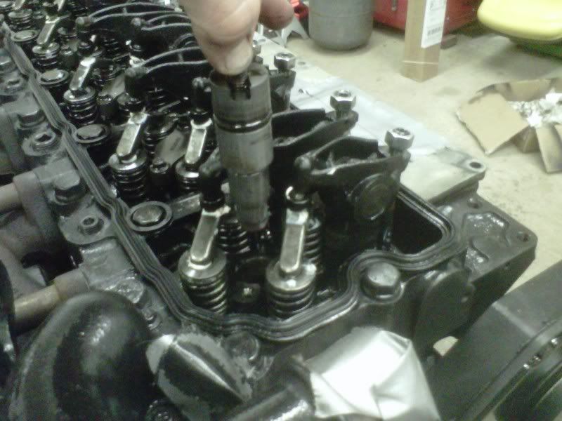
Then use the capscrew as a handle and lift the injector straight up.
IMG-20120716-00375.jpg


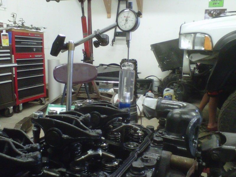
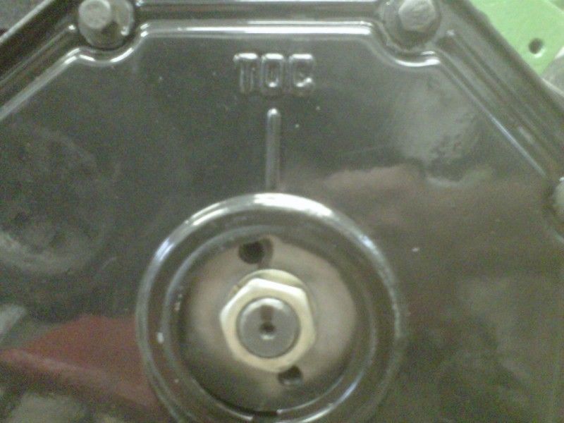
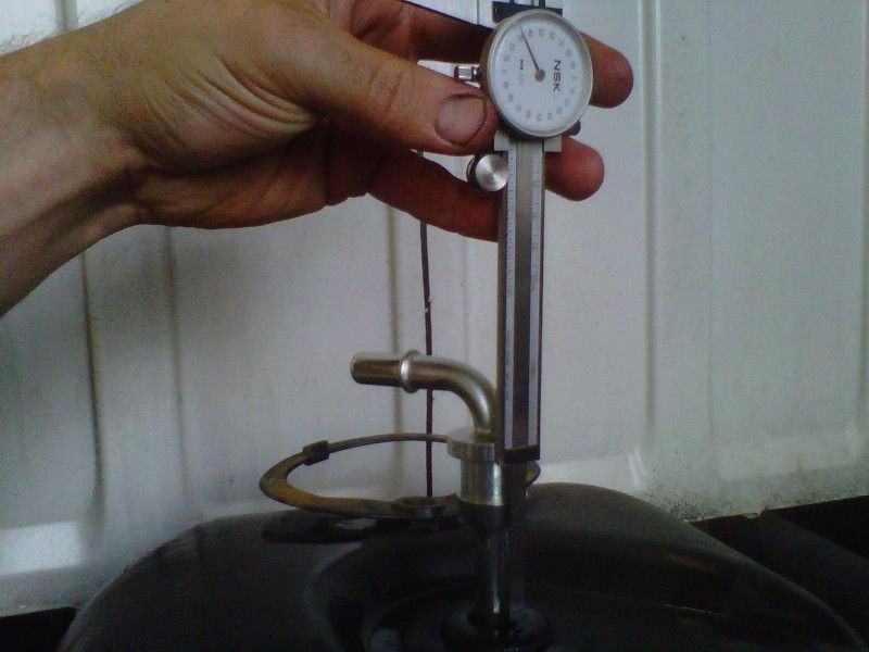
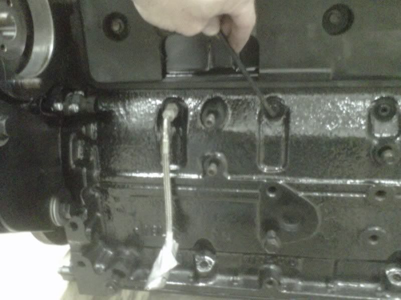
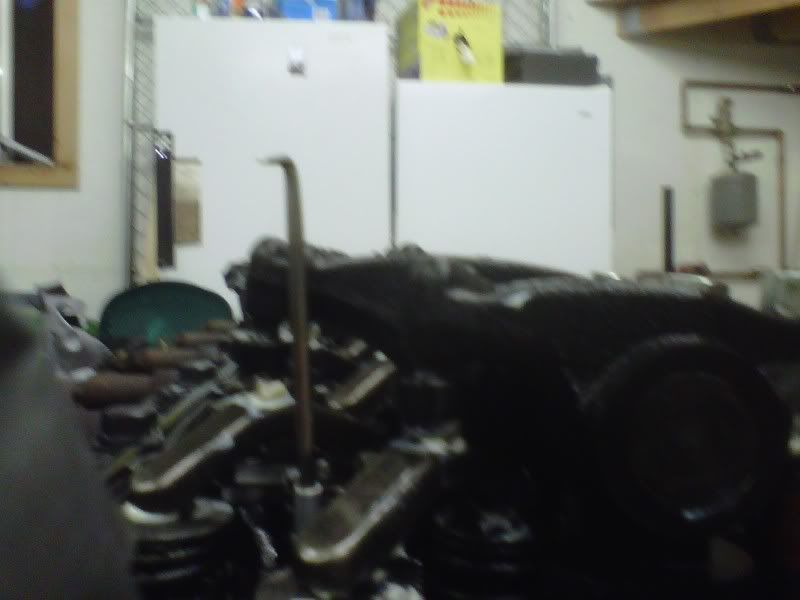
Since finding the exact TDC for setting the valves isn't critical, I simply used my double-ended pick to show the movement of the piston by gently placing it in the #1 injector hole.
IMG-20120716-00378.jpg


My hands were pretty gouped up so I don't think I took any pics of setting the valves. It wasn't too exciting anyway. haha

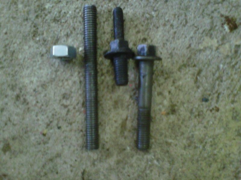
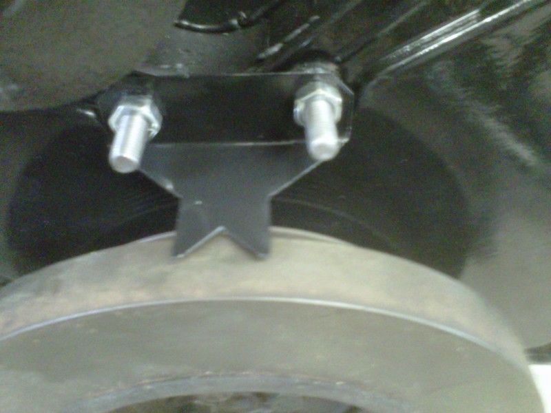
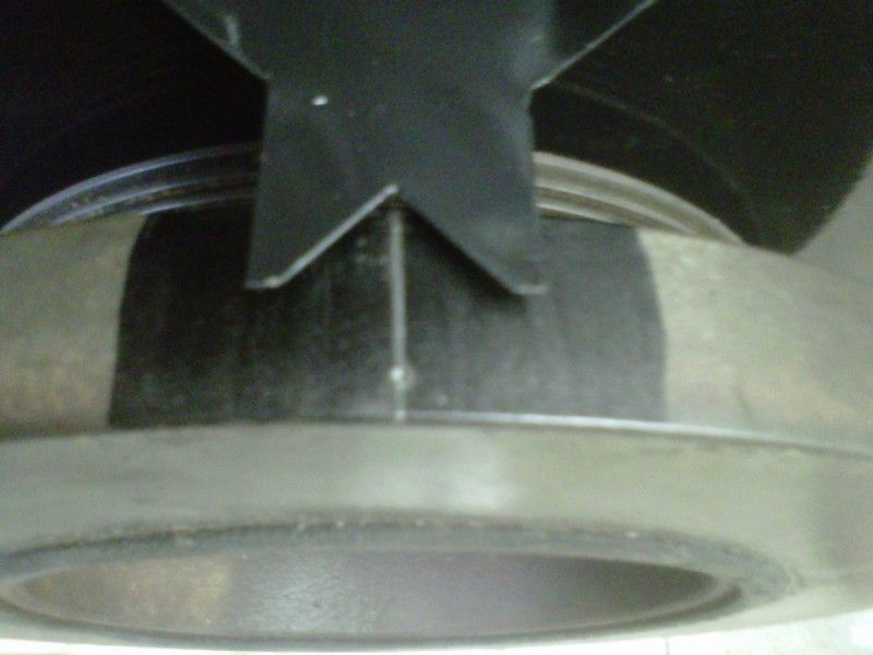
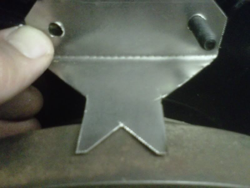
Tonight on the way home I bought some 22gauge sheet metal and some tin snips to make a TDC pointer. I'm pretty happy with the way it turned out.
IMG-20120719-00392.jpg


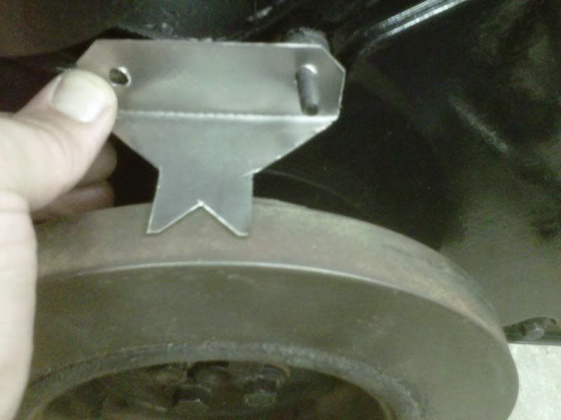
I just need to stop by the local Fastenal to get another double ended capscrew for the other mounting point.
IMG-20120719-00393.jpg


Tomorrow my pilot bearing should be in at NAPA. I noticed that it didn't roll very smoothly so I need to pull the flywheel back off and change the pilot bearing. Oh well, better to do it now than AFTER I get everything put back together in the truck!
 
When setting the valves, you just need to watch for the overlap on #1 and #6 and follow the Cummins sequence.

The pointer looks good.
 
To finish making the mounts for my TDC pointer I needed to essentially combine the 2 bolts on the right hand side. I needed the length of the bolt on the far right added to the double ended capscrew in the middle. Fastenal just didn't have anything like that in stock so I settled for a 3 foot piece of M8 all-thread. I cut it to the desired length.
IMG-20120721-00394.jpg


After making the one stud, I 'had' to make the other to match!
IMG-20120721-00395.jpg


Pointer installed.
IMG-20120721-00397.jpg


Thanks to another good friend at work, I was able to borrow his dial indicator and magnetic base. Since I don't have a spring compressor, I used a philips screwdriver to touch the piston through the injector hole. I simply went 2 turns of the dial in each direction, marking the dampner each time. Then I measured the distance between the two marks with my calipers and divided by 2 to find the midway point, which is TDC.
IMG-20120721-00399.jpg


TDC marked on the dampner.
IMG-20120721-00405.jpg


Then I used my Blue Point timing kit (scored on ebay for $100!) to turn the pump to 5.0 mm of lift which correlates to 16.5 degrees advanced.
IMG-20120721-00406.jpg


Bolted the pump on the housing and marked the pump shaft to make sure it didn't moved any while I torqued the nut to 150 ft-lbs.
IMG-20120722-00411.jpg


Then I pulled out each head bolt one at a time, starting with the first bolt in the recommended sequence. I dipped it in fresh motor oil, wiped the excess off and torqued it to 100 ft-lbs. Then I marked the head of the bolt with a line so that I could tell how far it turned. I proceeded until I got to every head bolt. Then I kept the torque wrench at 100ft-lbs and went through the sequence again. After that I up'd the torque by 5ft-lbs, going through the entire sequence with the aim to finally hit 125ft-lbs. While I was at 115ft-lbs, I was almost done with the sequence when I felt a bolt turn much farther than the rest. Not wanting to break off a bolt or threads in the block, I stopped and ordered 2 new bolts from my local Freightliner dealer. I continued to bring the rest of the sequence to 115ft-lbs. When I got the bolts home, I pulled out the suspect head bolt and heard oil squish, that indicated that I was hydro-locking the hole and not getting a good torque reading. I verified that the bolt wasn't damaged by comparing the length of the used bolt and a new one. Both were the same length as far as I could tell. I torqued it down to 100ft-lbs, then brought it up to 115ft-lbs with the rest of the other head bolts. My thought was to leave it there at 115ft-lbs and not take my chances (chicken). But the next day I hit all of the bolts again at 115ft-lbs to double check their torque and I decided to push my luck! I made it through 120ft-lbs and was going for 125ft-lbs, when the first bolt in the sequence felt like it was turning way too much (based on how little they turned in the other steps). So I backed the wrench down to 122ft-lbs and was able to click them all off without any troubles!

Now I have the overhead torqued back down, and double-checked the lash, and the valve cover is on.

I started to install the injector lines and got through most of them when it was time to go back into the house.
 
Thanks Wonderwood!

I noticed that there is a small oil drip from my pump while it is just sitting. I put a red circle around the point that the oil is dripping from. My thought is to remove the cap and see if there is a copper washer or some type of seal that needs to be replaced.

Can anyone tell me what is behind the cap? I really don't want to be suprised by any springs jumping out.
oildrip.jpg
 
You will get about a half litre of oil come out of the gov. housing. So have a little container ready if you are concerned about oil on the floor.

I know its too late now, but where your TDC pointer is where the engine speed sensor is on a 12v. The bolts you were looking for exist, and they are on any (dodge) 12v.
 
Thanks for the reply AJenson, that eases my mind!

Tate, good tip on the oil. And at least the info is out there for other people to get the bolt that I was looking for. I only had the housing without the cover, so I didn't have any of the bolts to go along with it.
 
Thanks John and Thojer, I really appreciate comments like that! John, do you ever go on company trips out west? You'll have to stop out here sometime!

It turned out that the timing pin cap wasn't even finger tight. Easy fix!

John, here's one of my favorite videos from our property out in NY state. Fun times!
[ame="http://s29.photobucket.com/albums/c296/blu_by_u/?action=view&current=2008-12-22BigDodgeindeepsnow004.mp4"]2008-12-22BigDodgeindeepsnow004.mp4 video by blu_by_u - Photobucket[/ame]
 
Last edited:
I've been trying to get a bunch of last-minute things tidied up before we set the engine back in the truck. I just don't want to be sorry later that I rushed this whole job.

Here I finally connected the oil supply line from the block to the pump.
IMG-20120725-00415.jpg


Next I wanted to see what kind of interference there might be with the conversion lines and the grid heater because I couldn't help but notice that one of the fuel lines looked like it was routed just a little over the mounting surface of the Tunnel Ram that I installed.
IMG-20120726-00422.jpg


My fears turned out to be real, but I was able to tweak the #1 line with a couple of open end wrenches by using them as pry bars. I should've snapped a photo of how I used the wrenches. I'll try to do that. This photo shows how close the line still is to the intake. I feel MUCH better about the routing, but still wish it was a little better. There are some other lines that are too close to each other for my liking. I'm not too sure how I'm going to remedy those.
IMG-20120726-00424.jpg


At this point I'm getting VERY close to setting the engine back in the truck. I pulled the valve cover off to pour in the first gallon of oil and the 2 bottles of zinc additive. I don't have any data to this method, but after thinking this over for days I thought this made sense: I started off by pouring some oil throughout the head and on top of the rockers. I felt like some of the oil on top of the rockers might seep down to the pivot points. Then I stopped pouring after reaching about a half gallon. Then I took the 2 bottles of zinc and tried to pour them down each of the push rod holes in hopes that it might find it's way right to the cam by seeping around the little bit of clearance there is on the lifters. After that I followed up by pouring in the rest of my first gallon of oil.
IMG-20120727-00427.jpg


IMG-20120727-00428.jpg


Now I've prepped the engine to be lifted into the truck. Notice that I had to remove the #5 and #6 injection lines? They interfered badly with the rear lift bracket.
IMG-20120727-00430.jpg


We've pushed the engine to in front of the truck. (Sure looks a LOT better going in than it did coming out! - well, in my opinion anyway)
IMG-20120727-00431.jpg


Here the engine is FINALLY back in the truck! I forgot to take many pictures, they would've probably been pretty boring. It didn't go in too tough, thankfully. We had to reposition the cherry picker once and still twist the engine while it was on the chains to get it to line up. Oh and I had to use my floor jack to lift the front end of the transmission up a little for alignment purposes. I still had the ratchet strap holding it up, hooked on both sides of the frame.
IMG-20120727-00432.jpg


Just another picture of the engine sitting in the frame.
IMG-20120727-00433.jpg


What the heck, here's another photo. I was pretty happy that this milestone was crossed! This was 11:30pm Friday night.
IMG-20120727-00435.jpg


Since these pictures I have:
  • connected the exhaust to the turbo
  • bolted up the starter
  • taken off the rear lift bracket
  • installed #5 and #6 injection lines
  • connected the engine harness to the vehicle harness and secured it
  • connected the power tap on the engine harness to the fuse box
  • re-installed the pyrometer probe to the fitting in the exhaust manifold
Sure doesn't seem like much to me for a Saturday and Sunday, but I took a little family time in there.....maybe more than a little.
 
I got some bad news from the local welder that I took my CAC to fix a spot that was failing the bubble check. Looks like the crack goes in too deep to get his welder in. I'll be calling up the local radiator repair guy and see if there is anything else that I could try. Anyone have any tips or ideas?
 
Looks like I'll be buying a used stock CAC. Oh well, could have been worse.

Tonight I cut the hose feeding the P-pump from the AirDog to length, wired the AirDog, and nearly finished wiring the fuel shutoff solenoid. I only need to find a good 12volt signal for the hold coil. What/where does everyone tap into for the hold coil?
 
Thanks guys, that answered my question. Since I literally JUST made that connection for my AirDog install, I measured the current draw of the AirDog and the solenoid to verify that together they drew less than the 2 Amp fuse and I just made a nice splice into the AirDog tap. Works like a charm.

Now I need to catch up on some pictures and progress!
 
Sorry for the delay. I've been pretty busy trying to make progress on the truck, work, and keeping the family happy.

My son and I went to the local hardware store to buy some plastic tubing and fittings to plumb in the boost reference in with my boost gauge. I pulled out the fitting from AFC housing and brought it with me. I noticed that the fitting had a pretty small opening at the base verses the same part at the hardware store. My thought is that the larger opening will allow the boost signal to get to the AFC housing a little faster.
IMG-20120801-00451.jpg


Here it is all plumbed up.
IMG-20120801-00453.jpg


This is a close up of the port that I use in the head. There's a pipe plug from the factory that I removed (a LONG time ago) and installed the reducer. When I just had to worry about the boost gauge, that fitting went straight into the reducer. Now that I need a boost reference to the pump, I bought a "T" fitting to make it all work like this. Not sure if I like the idea of a fitting like that hanging off the side of my engine, but it will do for now until I decide differently.
IMG-20120801-00456.jpg


Then I directed my attention to the power steering pump and swapping over the data plate from my original gear housing.
IMG-20120803-00467.jpg


Now the freon compressor is bolted to the engine.
IMG-20120803-00468.jpg


I'm really feeling like I'm starting to run out of things to put back on the engine so I decided to put the fan back on. Not sure if everyone does it this way, but I unbolted the pulley from the hub (6 or 8 little bolts) so that I could get to the last bolt that holds the bracket to the block. This is me bolting the pulley back to the hub.
IMG-20120804-00471.jpg


Here is the engine with the fan bolted on.
IMG-20120804-00472.jpg
 
So I'm going to fess up and just admit that the thought of drilling a hole in the top of my tank to install my AirDog 150 scared me to death. I saw different methods and locations that people used all over the internet. And I definitely didn't want to have the dreaded 1/4 tank syndrome (where the gauge shows 1/4 tank, but the truck is out of fuel). I talked it over with MoparMan1973 and Chris Snyder to get some first hand experience and help calm my nerves about the whole process. Here's how it went:

First I built my confidence up by tackling an easier task. I installed the return "T" into the filler neck.
IMG-20120804-00474.jpg


Then I used a holesaw to cut a 1 1/8" hole in the top of the tank, in the high spot between the factory hole and the cab of the truck. MoparMan mentions to place a quarter on the bottom of the tank and rest the new suction tube on top of the quarter (make sure to remove as much fuel as possible from the tank first).
IMG-20120804-00476.jpg


Then measure the difference between the top of the grommet and the top of where the suction tube rests on the grommet.
IMG-20120804-00478.jpg


Then cut that length off the end of the tube.
IMG-20120804-00479.jpg


MoparMan also advises to cut notches at the bottom of the tube to help prevent the tube from sucking flat to the bottom of the tank.
IMG-20120804-00480.jpg


Then the suction tube slips right in the grommet and is just barely off the bottom of the tank.
IMG-20120804-00481.jpg


I know this pic doesn't look much different than the one before, but I'm showing the suction tube installed and still just barely touching the quarter.
IMG-20120804-00482.jpg


I didn't take any pictures of the hoses all hooked up and routed, but I was sure to get a picture of the bed FINALLY back on the truck!
IMG-20120804-00483.jpg
 
Now it's REALLY feeling like I'm getting close to finishing up. It's time to install the throttle and the cruise control cable (you know, just in case I am able to get cruise to work on this truck haha). I had to unbolt the Throttle sensor from the bracket so that I could plug in the cables and the fuel fitting from AirDog.
IMG-20120805-00486.jpg


All bolted back up.
IMG-20120805-00487.jpg


I installed the shutoff solenoid and the wire harness that I bought from LarryB's. I sure wasn't too proud of the sky blue conduit that came with the solenoid.
IMG-20120805-00488.jpg


So I fixed it.
IMG-20120805-00490.jpg


I also wired up the AirDog at this point. Sorry that I didn't get any pictures of the wiring. Thanks to Chris Snyder and Kleann for the tip on where to tap into for the "Run" solenoid circuit. I was getting ready to use the power wire for the VP44 connector and really didn't want to go that route. The fuse tap in the door jam is MUCH better.
 
Back
Top