Michael
Comp Diesel Sponsor
Episode 16:
First off I would like to thank everyone who came out to the ISSPRO Pacific Coast Diesel Nationals! Despite sweltering heat we had an awesome turnout of fans and racers, and got to see some awesome racing and sled pulling. We fed the most people yet at our BBQ (despite this being the 1st year of not running gassers at the same time). They did have a gasser "Top Comp" shootout with a limited field, just to serve as filler between the diesel classes. I hoped the big purse would bring even more Super-Street trucks out of the woodwork, but I know a few teams had problems and couldn't make the race, while others broke at the event before eliminations! I was forunate enough to come out with a runner-up again in Sportsman ET, regaining the lead in National points by a single round! I was also foolish enough to tackle singing the National Anthem for the event, doing it acapella and with almost no sleep!
Between that event and other recent events, I have been pleasantly surprised by how many people (many of them not directly involved in the diesel performance industry) approached me to say they are following this build (and a few of you gave me some well-deserved grief for the length of time since my last update)!
Back to the race truck!
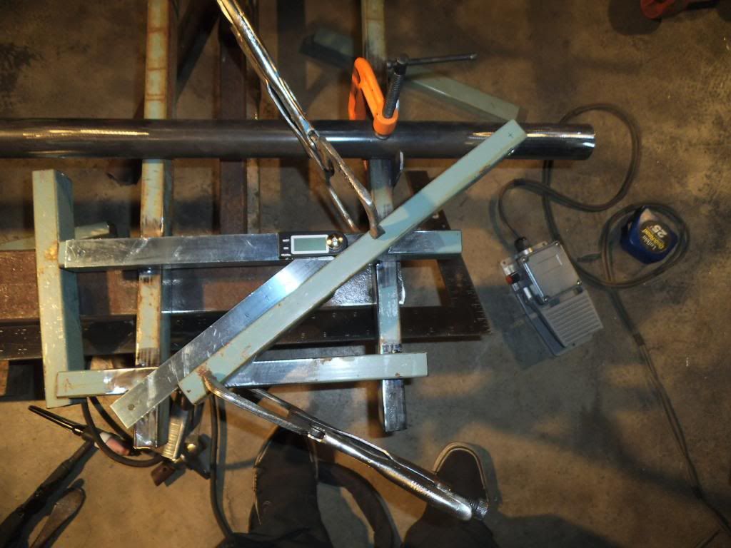
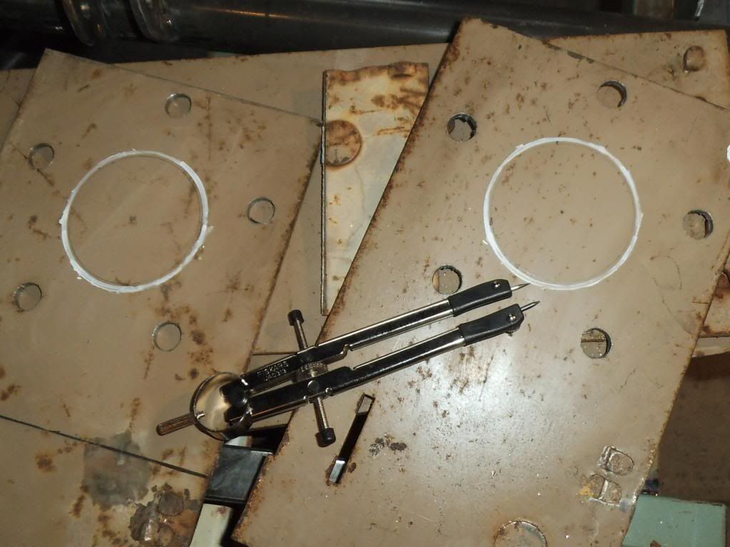
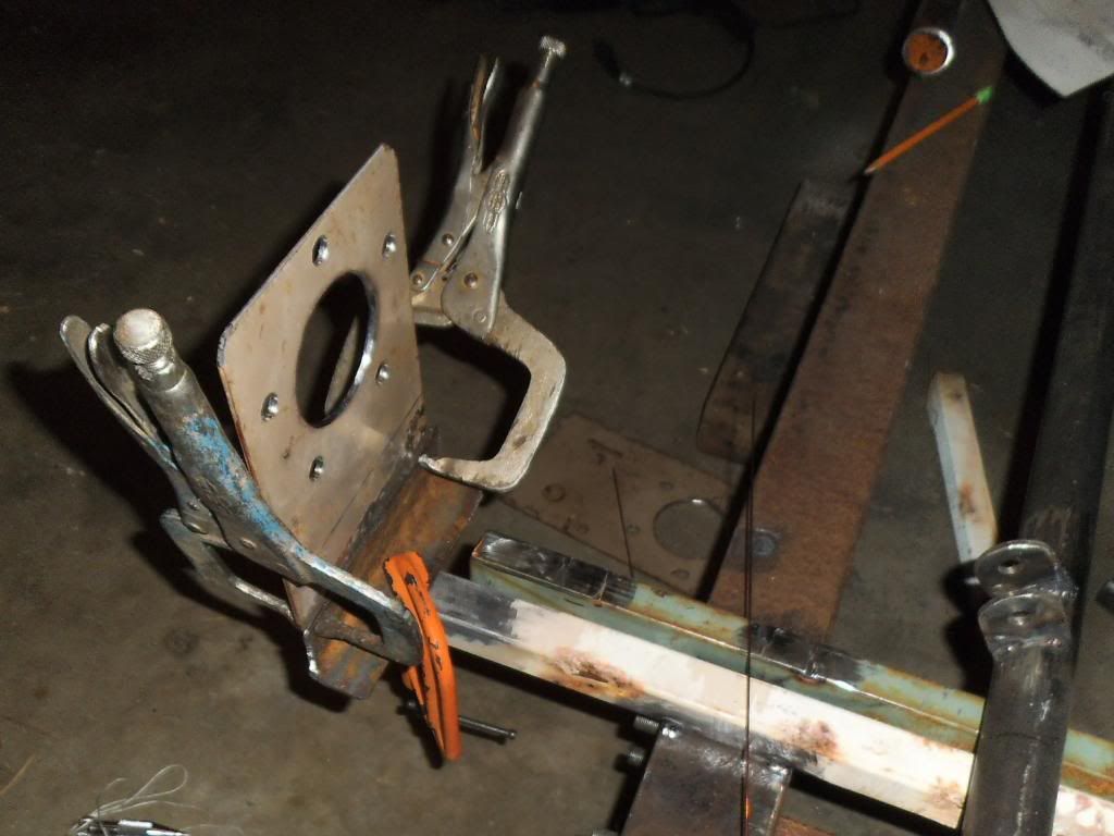
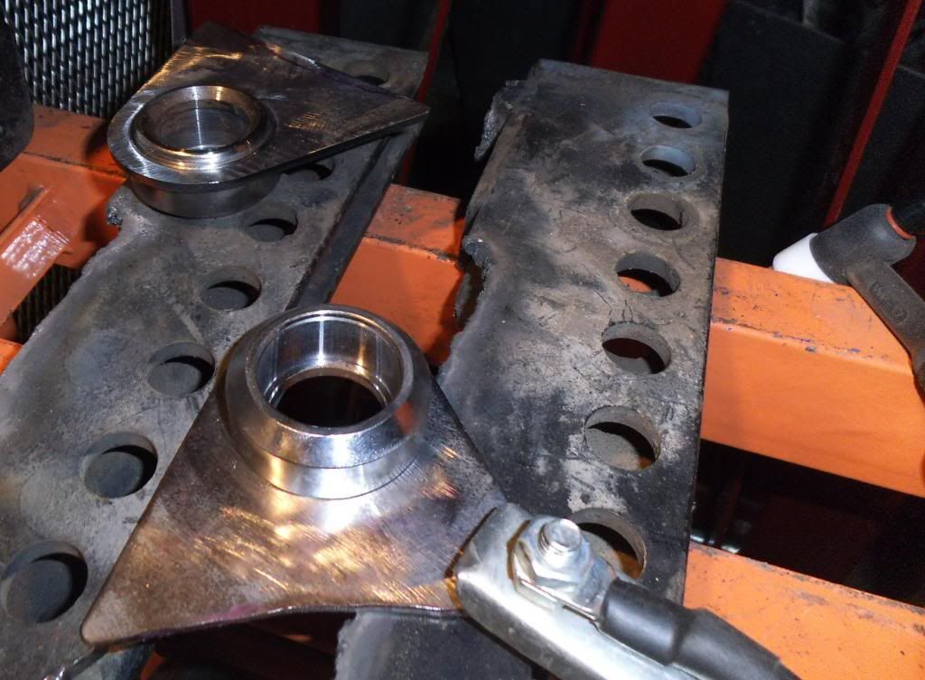
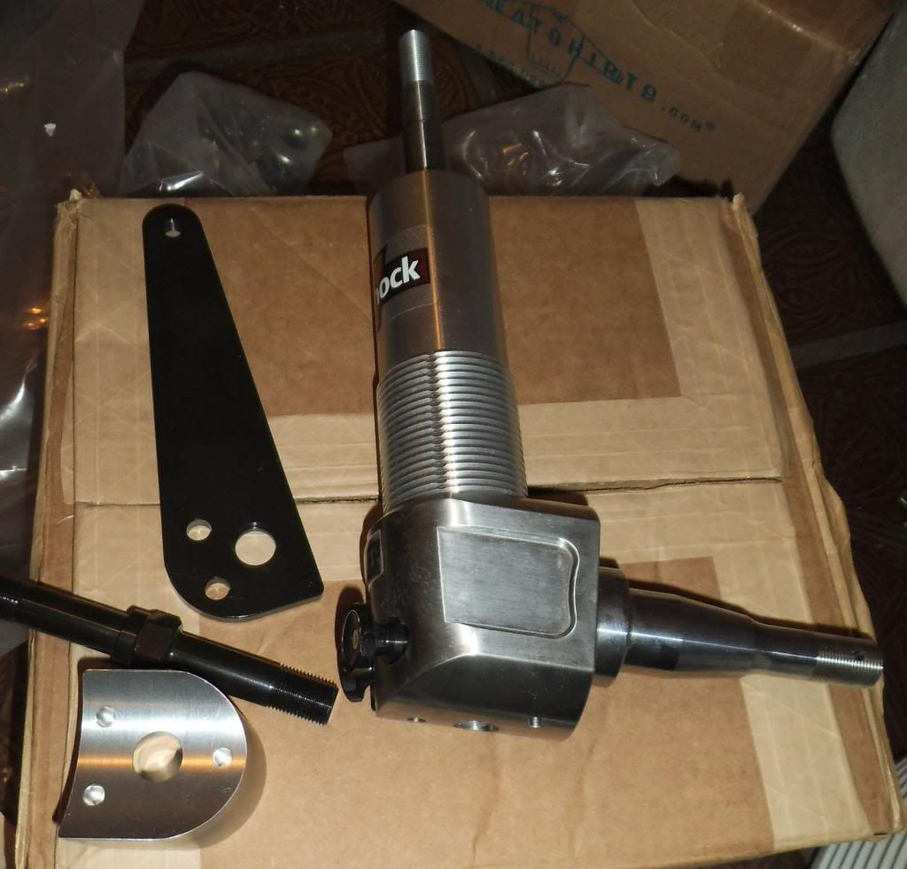
Next step was to build the lower control arm mounts. These were at strange angles in 3D space, and despite creating them in my 3D CAD model I decided to hand-fit them to minimze gaps. I carefully built jig "extensions" which positioned tubes in the same location as the strut control arms will be.

After that I made cardboard mockups of the brackets to test-fit the shapes on the tubing. You know those annoying subscription cards that come falling out of your new Diesel Power magazine as soon as you open it? I finally figured out a use for them in this step!
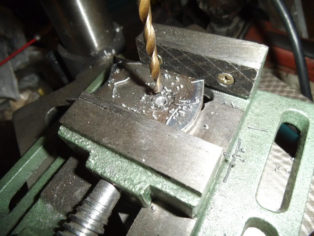
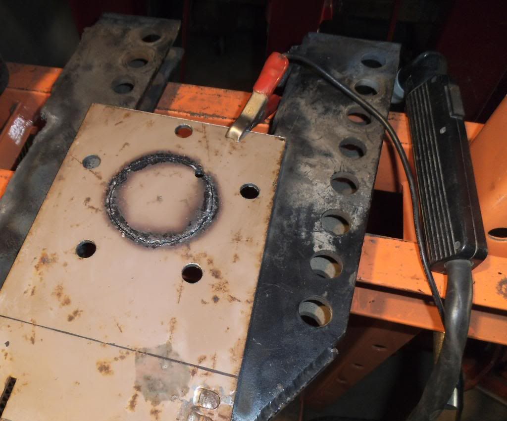
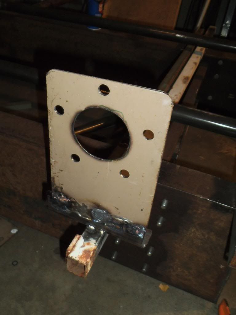
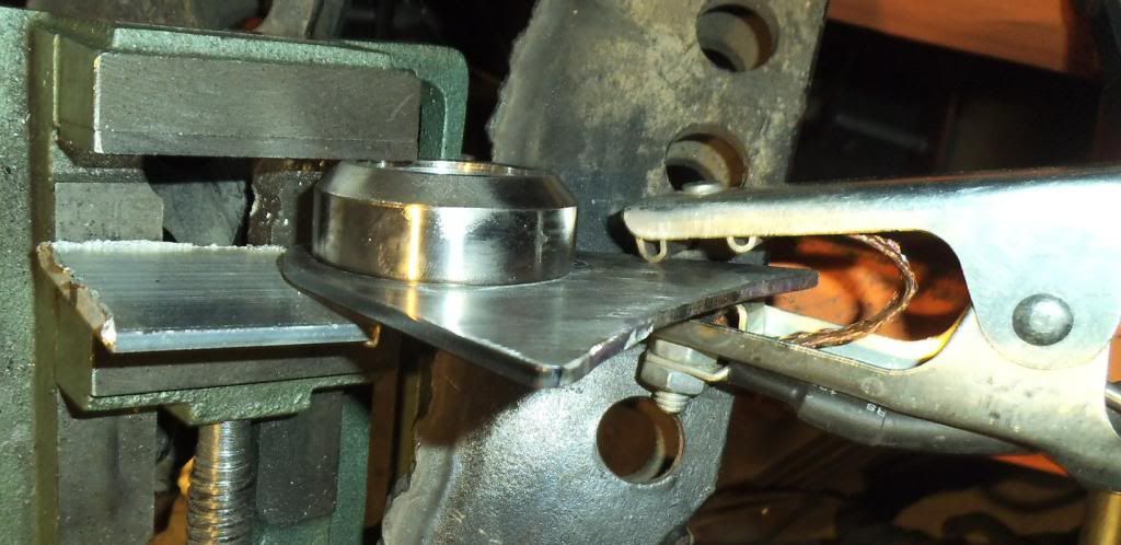
After the first piece I actually switched over to used gift cards as my test mockup models for the brackets, as they were a little less flimsy than the subscription cards. Once I had the shape nailed down I traced it onto a piece of 3/16" thick 4130 plate (previously sheared into appropriate width strips on my dad's big ironworker press), then rough cut the shape using my plasma cutter. After drilling the holes and finish shaping with a carbide burr or grinding wheel, I had my perfectly-fitted brackets.
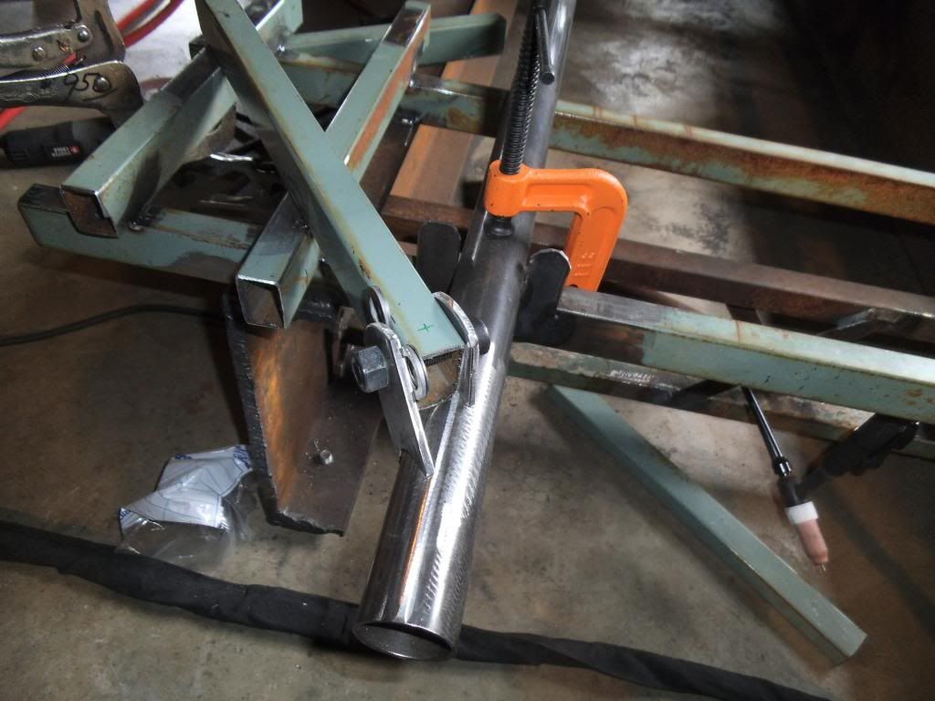
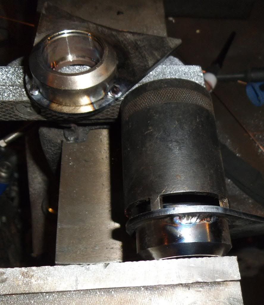
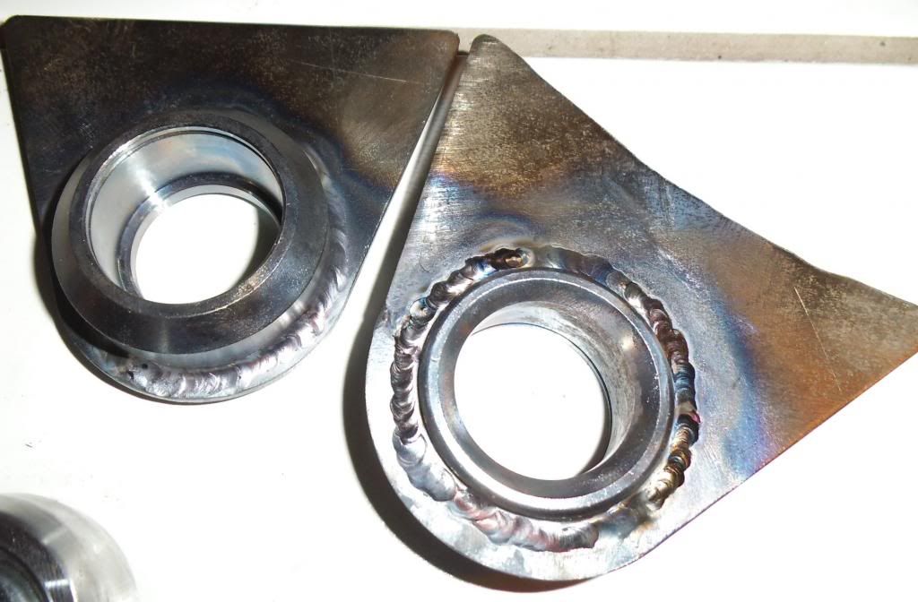
I carefully tack-welded these in, then skip-welded (short beads in alternating locations) while still anchored in the jig.
Next up it became evident that I really needed to get some better paint on this thing for the upcoming ISSPRO event. I started going over the cab and checking out various imperfections and cracks. I was surprised to find many voids in the original fiberglass surface, where they left a large air pocket when laying it into the mold.
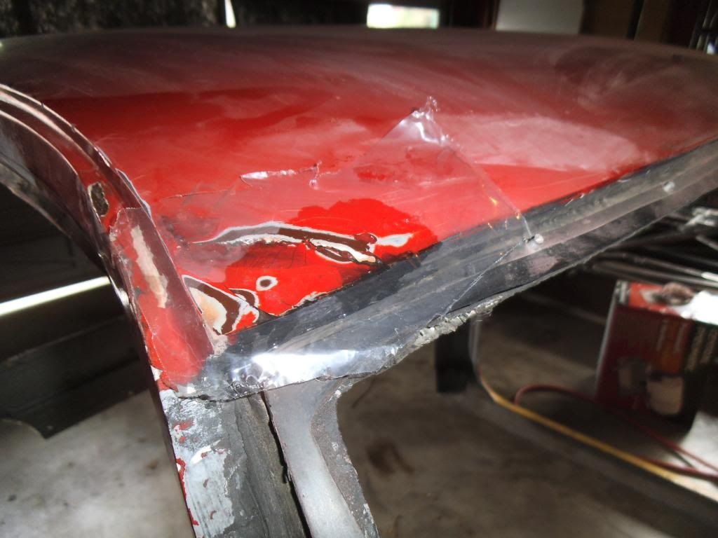
A few of those were significant and also showed up as cracks, needing some repair work. I used an old trick of laying a sheet of plastic (like from a heavy plastic bag) over the repair to smooth it out while it cured. This helped me force the resin into the recesses from the voids in the surface.
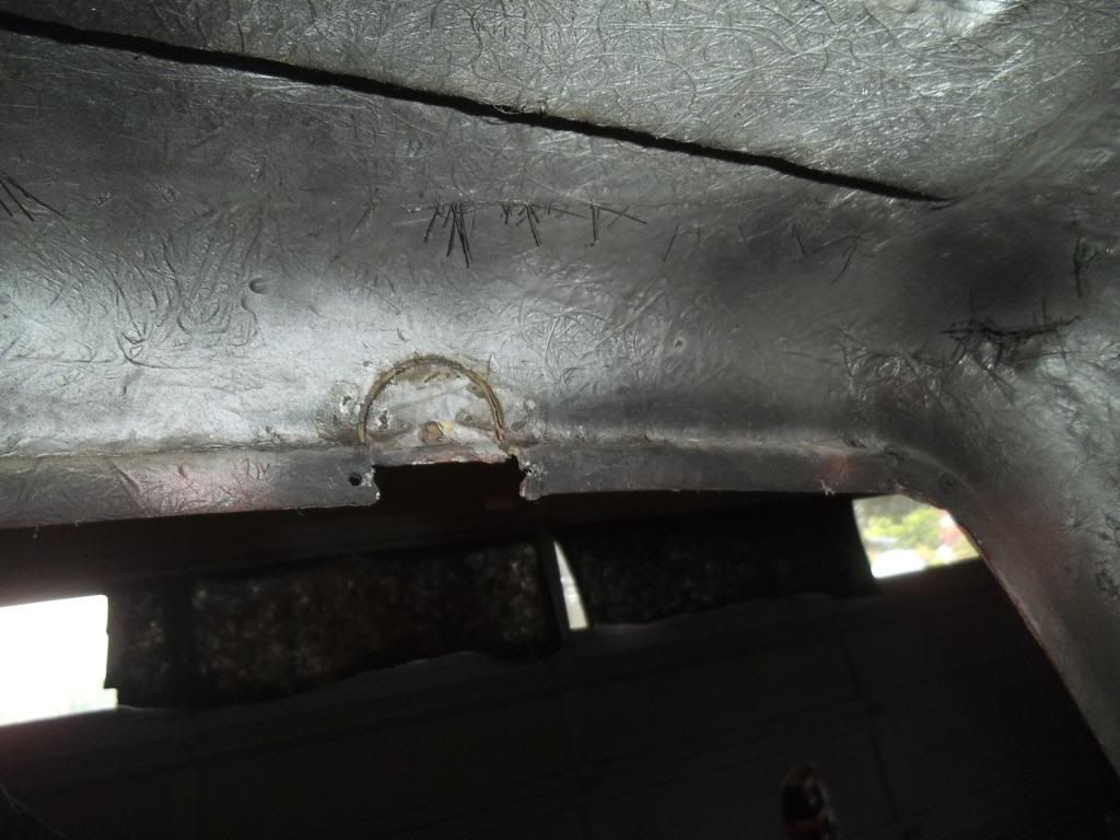
I also found cracks in a really cheezy patch job, where they had filled in from prior roll cage rear bars.
I patched these and filled in with resin and mat, knowing that my rear bars will be at a different width anyway.
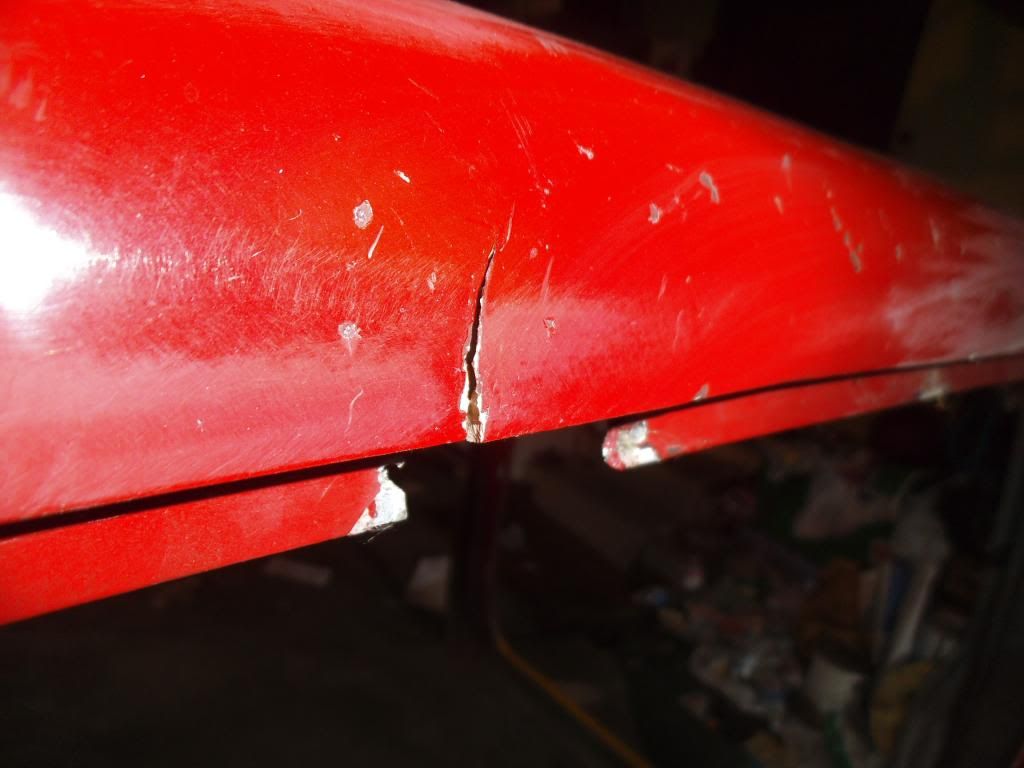
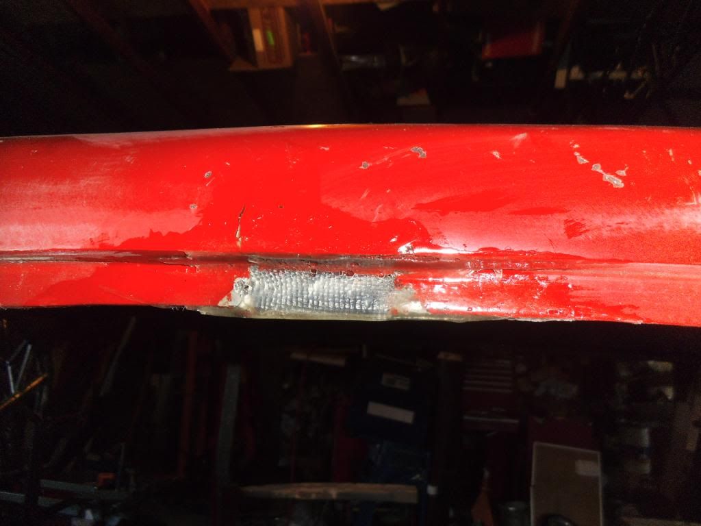
The driver's A-pillar on the cab turned out to be really bad, with huge voids in it that turned into a complete break.
I had to use a piece of flat stock to reinforce that area, and fully glassed-in the piece as part of the repair.

Next up was shortening the bed from 7' to 6', to match my shorter wheelbase, After trying a couple of methods, the cleanest cut was with a cutoff wheel in an angle grinder.

I also had to remove all traces of old stickers from the panels, this was quite a chore requiring a heat gun, scraping, a couple of chemicals, and maybe a cuss word or two...
At this point I hauled the whole mess over to the ISSPRO factory and set up shop outside the paint booth. We have a professional-quality paint booth for spraying industrial coatings, so it was nice to not have to do this in my garage!
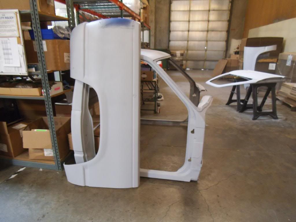
I shot several coats of primer and sanded between coats.
After the primer and finish sanding I was ready to shoot some color and clear.
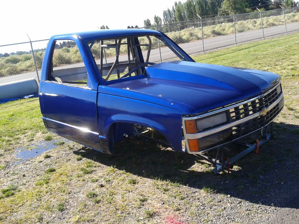
I assembled things (including getting the grille in upside down for this photo) and hauled them out to the track for display at our race. As of 1:00 Saturday morning I had been running on about 4 hours of sleep since Tuesday morning!
Of course I put a ton of scratches in my fancy new paint hauling it back and forth from the track, but at least it is starting out looking reasonably nice (compared to my Vega that still has the same primer and damage from 1988)!
First off I would like to thank everyone who came out to the ISSPRO Pacific Coast Diesel Nationals! Despite sweltering heat we had an awesome turnout of fans and racers, and got to see some awesome racing and sled pulling. We fed the most people yet at our BBQ (despite this being the 1st year of not running gassers at the same time). They did have a gasser "Top Comp" shootout with a limited field, just to serve as filler between the diesel classes. I hoped the big purse would bring even more Super-Street trucks out of the woodwork, but I know a few teams had problems and couldn't make the race, while others broke at the event before eliminations! I was forunate enough to come out with a runner-up again in Sportsman ET, regaining the lead in National points by a single round! I was also foolish enough to tackle singing the National Anthem for the event, doing it acapella and with almost no sleep!
Between that event and other recent events, I have been pleasantly surprised by how many people (many of them not directly involved in the diesel performance industry) approached me to say they are following this build (and a few of you gave me some well-deserved grief for the length of time since my last update)!
Back to the race truck!
Next step was to build the lower control arm mounts. These were at strange angles in 3D space, and despite creating them in my 3D CAD model I decided to hand-fit them to minimze gaps. I carefully built jig "extensions" which positioned tubes in the same location as the strut control arms will be.
After that I made cardboard mockups of the brackets to test-fit the shapes on the tubing. You know those annoying subscription cards that come falling out of your new Diesel Power magazine as soon as you open it? I finally figured out a use for them in this step!
After the first piece I actually switched over to used gift cards as my test mockup models for the brackets, as they were a little less flimsy than the subscription cards. Once I had the shape nailed down I traced it onto a piece of 3/16" thick 4130 plate (previously sheared into appropriate width strips on my dad's big ironworker press), then rough cut the shape using my plasma cutter. After drilling the holes and finish shaping with a carbide burr or grinding wheel, I had my perfectly-fitted brackets.
I carefully tack-welded these in, then skip-welded (short beads in alternating locations) while still anchored in the jig.
Next up it became evident that I really needed to get some better paint on this thing for the upcoming ISSPRO event. I started going over the cab and checking out various imperfections and cracks. I was surprised to find many voids in the original fiberglass surface, where they left a large air pocket when laying it into the mold.
A few of those were significant and also showed up as cracks, needing some repair work. I used an old trick of laying a sheet of plastic (like from a heavy plastic bag) over the repair to smooth it out while it cured. This helped me force the resin into the recesses from the voids in the surface.
I also found cracks in a really cheezy patch job, where they had filled in from prior roll cage rear bars.
I patched these and filled in with resin and mat, knowing that my rear bars will be at a different width anyway.
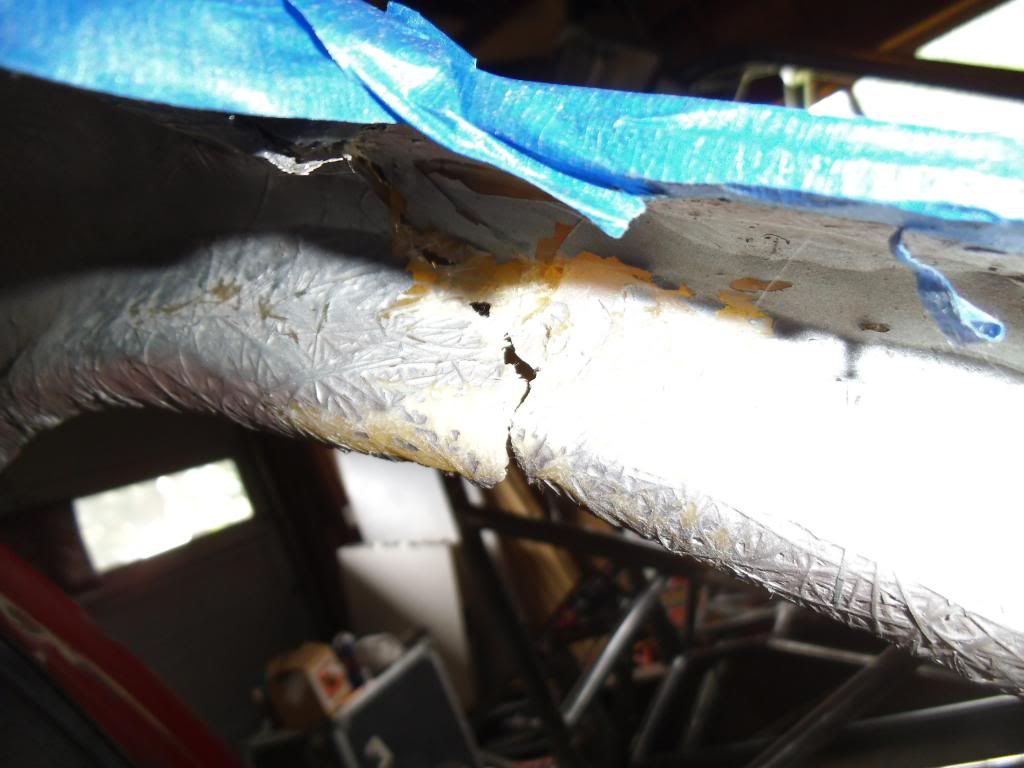
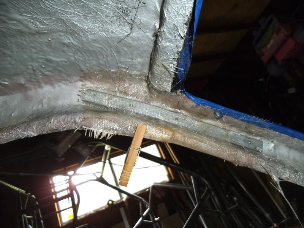
The driver's A-pillar on the cab turned out to be really bad, with huge voids in it that turned into a complete break.
I had to use a piece of flat stock to reinforce that area, and fully glassed-in the piece as part of the repair.
Next up was shortening the bed from 7' to 6', to match my shorter wheelbase, After trying a couple of methods, the cleanest cut was with a cutoff wheel in an angle grinder.
I also had to remove all traces of old stickers from the panels, this was quite a chore requiring a heat gun, scraping, a couple of chemicals, and maybe a cuss word or two...
At this point I hauled the whole mess over to the ISSPRO factory and set up shop outside the paint booth. We have a professional-quality paint booth for spraying industrial coatings, so it was nice to not have to do this in my garage!
I shot several coats of primer and sanded between coats.
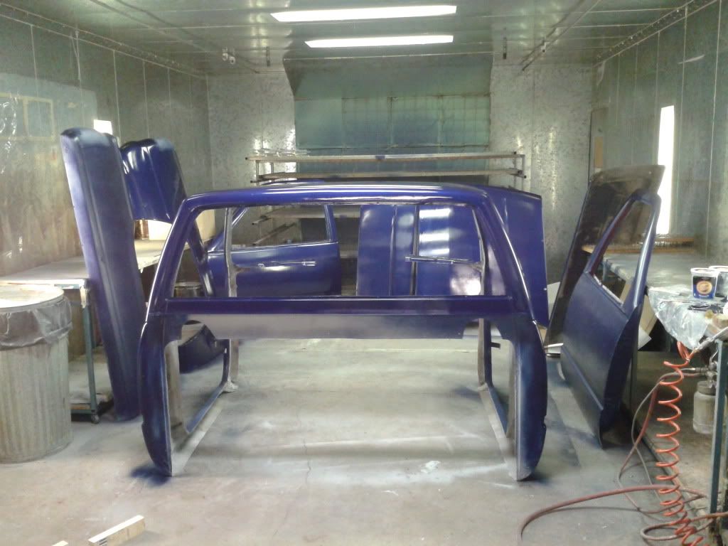
After the primer and finish sanding I was ready to shoot some color and clear.
I assembled things (including getting the grille in upside down for this photo) and hauled them out to the track for display at our race. As of 1:00 Saturday morning I had been running on about 4 hours of sleep since Tuesday morning!
Of course I put a ton of scratches in my fancy new paint hauling it back and forth from the track, but at least it is starting out looking reasonably nice (compared to my Vega that still has the same primer and damage from 1988)!