2013 3500 wiring diagram

mpeters0991

New member
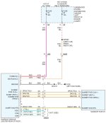
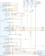
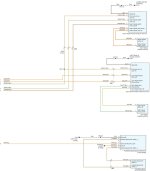
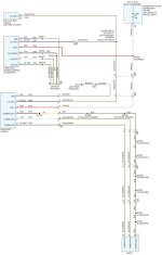
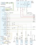
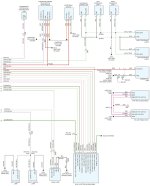
I’m looking for a cab wiring diagram if anyone has one. I’m having an issue where my sunroof, rear sliding window, third brake light, back up camera in the third brake light, and 3 lights between the bumper and tail gate won’t work. Everything else in the panel with the switches for the sunroof and rear slider work. Any ideas or suggestions would be appreciated!


Sent from my iPhone using Tapatalk
 
attachment.php


attachment.php


attachment.php


attachment.php


attachment.php


attachment.php
 

Attachments

  • sunroof.jpg
    sunroof.jpg
    92.3 KB · Views: 0
  • Windows A.jpg
    Windows A.jpg
    196.3 KB · Views: 0
  • Windows B.jpg
    Windows B.jpg
    113.1 KB · Views: 0
  • Camera A.jpg
    Camera A.jpg
    102.4 KB · Views: 0
  • Tail Lights A.jpg
    Tail Lights A.jpg
    261.8 KB · Views: 0
  • Tail Lights B.jpg
    Tail Lights B.jpg
    177.3 KB · Views: 0
So for the 30 amp fuse (f35) it’s supposed to always be hot but I am getting no reading from it. I took the fuse box out and looked at the back of it and it appears everything is as it should be. Not sure where to check now. I’m a rookie when it comes to electrical. The other fuse f66(10amp) is showing voltage as it should when in the run position. IMG_3581.jpg


Sent from my iPhone using Tapatalk
 
Also on another note I forgot what one wire was that was hooked up to a battery and it had an inline fuse so I just checked that for the heck of it and it looked pretty bad. Wasn’t blown but looked like it got hot. The wire I ended remembering is for the compressor for my Kelderman air ride (viair compressor). I cycled the compressor and the wire did get fairly warm. Would this indicate the compressor is going bad and drawing too many amps? It had a 30 amp fuse in it but on keldermans site it looked like it had a 20 amp fuse with it so I ended up swapping a 20 in there.
 
So for the 30 amp fuse (f35) it’s supposed to always be hot but I am getting no reading from it.

Appears that you have an issue in your power distribution then if your 30A isn't hot. Maybe Scott has a diagram further up the line.

Also on another note I forgot what one wire was that was hooked up to a battery and it had an inline fuse so I just checked that for the heck of it and it looked pretty bad. Wasn’t blown but looked like it got hot. The wire I ended remembering is for the compressor for my Kelderman air ride (viair compressor). I cycled the compressor and the wire did get fairly warm. Would this indicate the compressor is going bad and drawing too many amps? It had a 30 amp fuse in it but on keldermans site it looked like it had a 20 amp fuse with it so I ended up swapping a 20 in there.

Fuses are there to protect wiring, not devices, or...if you want to protect the devices, then the wiring needs to be at least larger than the fuse. If that compressor wire had a 30A fuse in it at some point, then it needs to be at least a 10 awg wire. If you drop the fuse to a 20A, then the wire needs to be at least 12 awg. What size wire is it? If it is a 14 awg wire or something and was fused at 30A and the compressor pulls hard, it will get hot. Voltage drop becomes an issue with smaller wire as well. It lowers the voltage on the end of the wire and the load will pull more current to compensate.
 
Appears that you have an issue in your power distribution then if your 30A isn't hot. Maybe Scott has a diagram further up the line.


Fuses are there to protect wiring, not devices, or...if you want to protect the devices, then the wiring needs to be at least larger than the fuse. If that compressor wire had a 30A fuse in it at some point, then it needs to be at least a 10 awg wire. If you drop the fuse to a 20A, then the wire needs to be at least 12 awg. What size wire is it? If it is a 14 awg wire or something and was fused at 30A and the compressor pulls hard, it will get hot. Voltage drop becomes an issue with smaller wire as well. It lowers the voltage on the end of the wire and the load will pull more current to compensate.


I would say the wires are at least 12 if not 10. I believe the system was installed by Kelderman years back so I’d think it would have been done correctly. I was doing some reading last night and on horn blasters they had a faq and were talking about a one way check Valve. If it fails then that could cause extra load in the compressor so I’m going to check that today.


Sent from my iPhone using Tapatalk
 
Maybe Scott has a diagram further up the line.

Not sure what you mean by "further up the line." It's in the Fuse Box/PDC or whatever it was called in '13. If it's not hot on the hot side of the fuse, it would be a problem in the panel, correct?

attachment.php
 

Attachments

  • Fuse Box.jpg
    Fuse Box.jpg
    392.7 KB · Views: 0
Not sure what you mean by "further up the line." It's in the Fuse Box/PDC or whatever it was called in '13. If it's not hot on the hot side of the fuse, it would be a problem in the panel, correct?

That's where I was going with "up the line". Meaning idirectely....the PDU is probably fried. Unfortunate, but possibly true. Not sure what all is between that fuse and the battery is my comment. :D
 
Gotcha. It looks like the same old PDC/TIPM configuration. Battery should be connected to the stud I circled. From there, I'd think there's a "strap" connecting the hot side of the proper fuses to the stud. I don't know, it's internal in the module.

attachment.php
 

Attachments

  • PDC.jpg
    PDC.jpg
    251.3 KB · Views: 0
Ya, I've never had one of those apart to see the guts. I would guess metal straps as you mentioned. If something huge was wrong, there would be more missing power than just that one fuse. Might have a strap burned? Who knows. Would take some diag.
 
I’ll have to look into that. Maybe I’m crazy but I didn’t see any straps or maybe I’m not looking at the right part of it. I had it off a little bit last night and you’re right it’s just a nut in that one stud that’s connected to the hot wire holding it (and some plastic snaps). Here is a crappy pic or how the back looked IMG_3580.jpg
IMG_3579.jpg


Sent from my iPhone using Tapatalk
 
I found this pic of the inside. There were also a couple YouTube videos about repairing them. Search “Ram TIPM repair.”

attachment.php
 

Attachments

  • IMG_0327.jpeg
    IMG_0327.jpeg
    105.3 KB · Views: 0
After I made that post I realized that’s probably what you meant. Thank you very much for all you’re help. I’ll give the videos a look.


Sent from my iPhone using Tapatalk
 
Well I got a new tipm and swapped it out and the my issues are still there. Not sure where to start now. Thinking about wiring issues is making my head hurt lol


Sent from my iPhone using Tapatalk
 
Back
Top