
gear_grinder
New member
im an idiot and posted this in the wrong place, sorry mods :nail:
Let me preface this by saying this is my own experiment, replicated at your own risk and discretion. This modification was done to a 1996 truck, no idea if other sending units vary in design and no guarantee that the pump will fit like mine did if they're different.
I came to diesels from the tuner/hotrod scene and frankly was appalled by the cost and design of some of the aftermarket lift pumps, along with monitoring my factory lift pump (new genuine cummins and gone through the system front to back for cleanliness) pressure at various loads and throttle inputs. my stock truck with the fuel plate removed and some other minor AFC tuning would pull fuel pressure down to nearly 10psi at WOT (adjustable overflow valve idle pressure at 30psi).
So I sat down and had a think about what I needed for my new truck. I have moderate goals for the my new (to me) 1996 dually with 76k original miles 1owner truck, I'd like to make around 400whp (a common goal for many i see on the facebook groups and forums). Many people claim the stock lift pump will do 400hp when shimmed, however i have my doubts after seeing how the pressure responded to my basically stock truck. I also was shocked by the price of the name brand lift pumps (airdog/fass), absurd amount of money for the fuel flow. There has to be a better solution....
Fleece offers a dual pump in tank kit for the 4th gen trucks now, and i believe that is the best solution for them. Why are in-tank pumps the best solution for performance and efficiency? here are some reasons:
1.) No draw straws or sumps. no cutting up your factory tank and losing your factory surge tank/baffle system.
2.) Stock 3/8" fuel line will support alot of power when under pressure. 1000+turbo ls cars are running 3/8" feed line, i doubt a 400-
600hp diesel will need more.
3.) Pump cooling. 90% of what I see in people posting about failed aftermarket lift pumps are from heat. a motor working in
nothing but air needs a ton if air flow and heat sync to keep cool. liquid cools a lot better than a gas does, its why we have liquid
cooled engines and why the OEs have been sticking pumps in the fuel tanks of all vehicles for years
4.) Pump feed pressure (this one is important). your pump is feed by pressure, that pressure is atmospheric pressure pushing on the
liquid. the same way you drink through a straw, you lower the pressure on one side of the hose/tube/straw and the fluid is forced
by atm pressure to the low pressure area. Exactly the same goes for your fuel system.
Ideally external pumps need a very large feed hose, much larger than the output hose because (if they are above the fuel level)
are fed only by a fraction of the ambient air pressure. Only a fraction? Yes, to get full atm pressure (14.7psi at sea level) you'd
need to somehow draw a perfect vacuum (which is basically impossible for a fluid transfer pump). At best, usually they will
create a pressure differential of about only 1-2psi. So how can this be improved? ever do a beer bong? it works because you
not only have atm pressure on the beer, but the WEIGHT of the beer itself pushing itself into your mouth. Same goes for fuel and
your lift pumps. TANGENT WARNING! if you put your external lift pump level or below the tank of fuel and had a sump on the
tank, you could feed it with the fuel column, but nobody is going to hang their $600-1000 fass below the tank level... but I
digress.
So leading back to the in tank fuel pump, the fuel inlet is basically at the bottom of the tank (.250"-.375" off of the bottom
usually), so the full height of the fuel column (fuel above the pump inlet) is working to feed the pump on top of the low pressure
area the pump creates giving superior fuel feed to nearly any external fuel pump system.
5.) Value. Cost is something thats relative to each person, I could have bought a high dollar big name pump setup, but I graduated
highschool at basically the height of the 2008 depression, my frugal parents and life experience has taught me to value money.
Dropping the level of cash on the big name systems just didn't sit well with me for what my needs were and their performance
value. We'll discuss the cost of the lift pump/fuel system setup with each component, but the basic setup could be easily
replicated for about $200-$250.
6.) power, pressure, and flow. stock/mildly modified p7100 pumps have shown to pickup power to about 40-50psi of delivered fuel
pressure. as tested by PDD, fass' "fuel polishing" valve cracks as a overpressure relief around 40psi (the pump is also not
delivering anywhere near the advertised number at that pressure either). The pump I selected delivers the advertised flow at
pressure and has an internal pressure relief valve that opens all the way up 150psi (not that the pump flows much there, but hey
better to have it and not use it right?).
7.) clean installation. no wires or hoses or pumps hanging all over the frame. I found my install to be a very clean/sanitary finished
product and look very OE including using the factory electric fuel pump circuit already built into the truck and harness
That's all I've got for benefits over a "conventional" aftermarket lift pump system...
Basic component list (just to get it going, i'll list the extras later):
Pump: AEM 50-1005, retail on amazon: $151 (https://www.amazon.com/AEM-50-1005-...coding=UTF8&psc=1&refRID=EPSBXTQG4H51SJ5561JD). Read the info on it here (pressure/flow data, amp draw data, etc...) https://www.aemelectronics.com/prod...-fuel-pumps/400lph-inline-high-flow-fuel-pump
inlet filter: AEM 50-200-11, retail on amazon $12.20 (https://www.amazon.com/AEM-50-200-11-Inlet-Filter-Inline-x/dp/B00VBH912E)
8an to 3/8" hose barb: Derale 98201, $4 (https://www.summitracing.com/parts/der-98201)
Tile Drain coupler (you'll see where this comes in later): $2 https://www.menards.com/main/plumbi...-c-9568.htm?tid=-7042517412670233045&&ipos=33
Misc screws, hose, and clamps $20-free99 depending on what you already have and your resources.
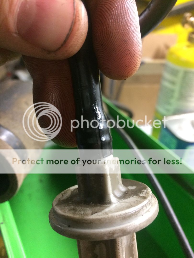
So first thing you need to do obviously is remove the tank and sending unit. I despise the factory nylon tubing they started using in the early 90s on everything for fuel line, you can keep it but I personally always remove it and replace it with high pressure rubber hose and clamps. easy way to remove it from fittings/tubing is cut it length wise along fitting/tubing. releases the tension and easily comes off. You do need to save the quick connect fittings on the tank however if you are going to keep the install as clean as possible.
heres cutting the nylon lines
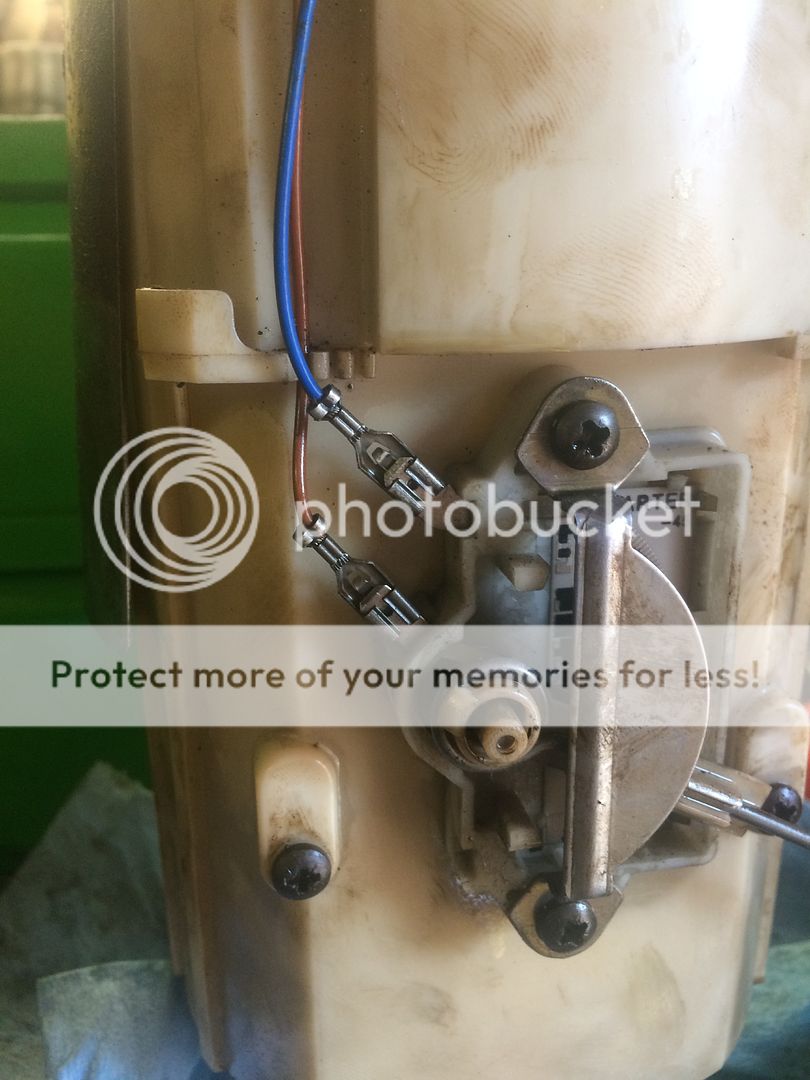
once you have the fuel sending unit out you can start disassembling it. first thing should be the three screws holding the top to the bottom half, go ahead and cut the fuel line that goes to the center pickup tube and disconnect the two spade connectors on the fuel level sensor !!BE EXTREMELY GENTLE WITH THE LEVEL SENSOR, I WAS NOT AND NOW HAVE TO TAKE THE TANK BACK OUT OF THE TRUCK TO FIX IT!!! the other two hoses going down into and along side the sending unit should just slide out with the top of the sending unit, leave these attached.
here's a picture of the level sensor and two wires
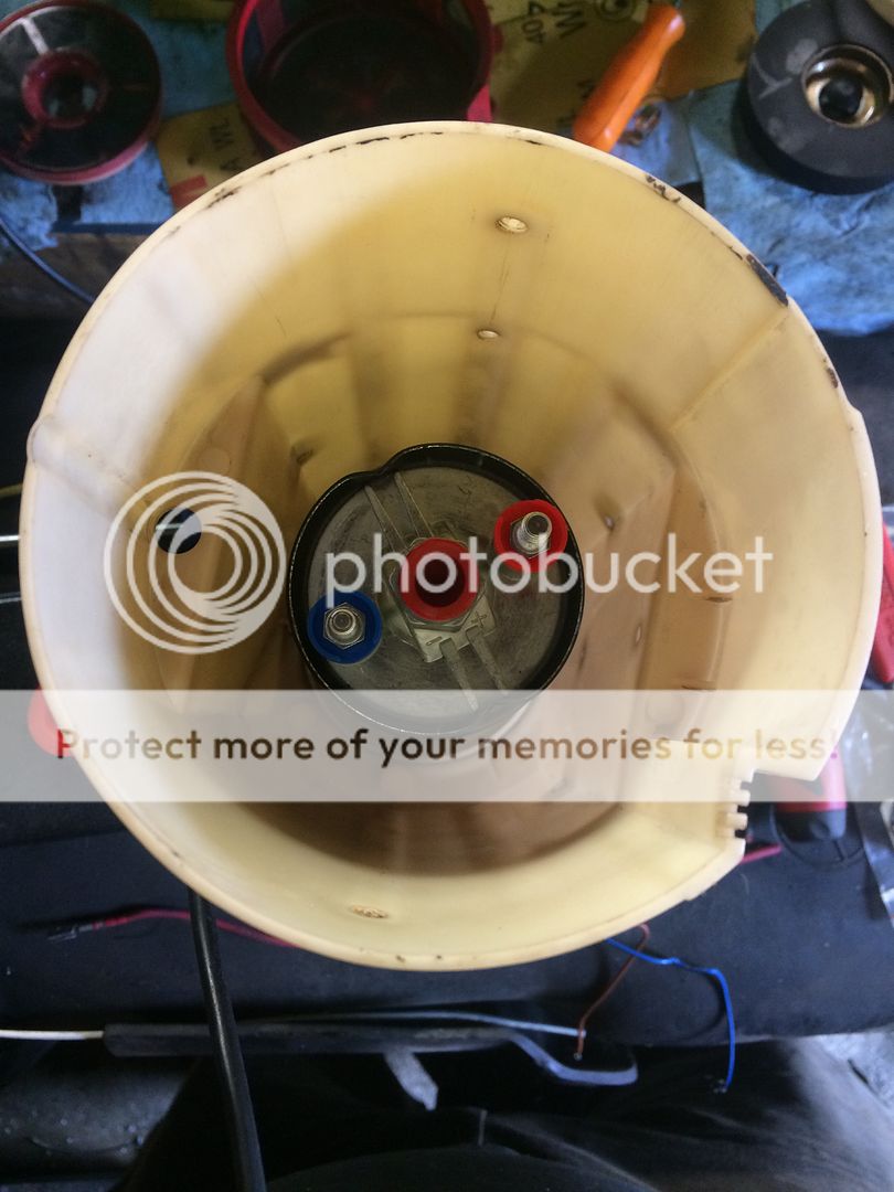
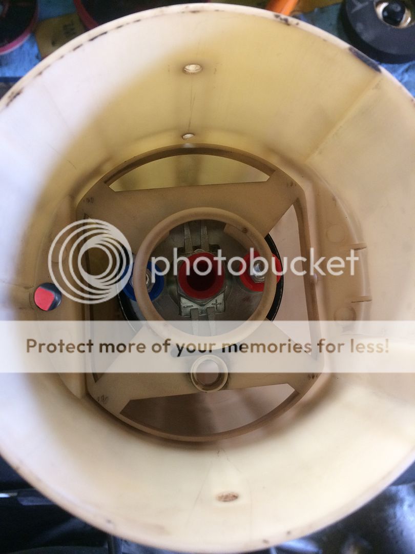
set the top of the sending unit aside for now, remove the level sensor from the side of the lower half of the sending unit (two screws) and set aside, remove pickup tube retainer, pickup tube, fuel return screen, fuel feed screen and fuel feed check valve/float (just pulls out from the bottom)
pickup tube retainer
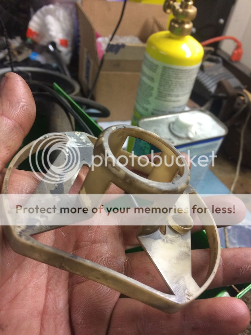
pickup tube
[ame]http://s5.photobucket.com/user/Temp2/media/1996%20ram%203500/IMG_4269_zpskx1gbwhe.jpg.html[/ame]
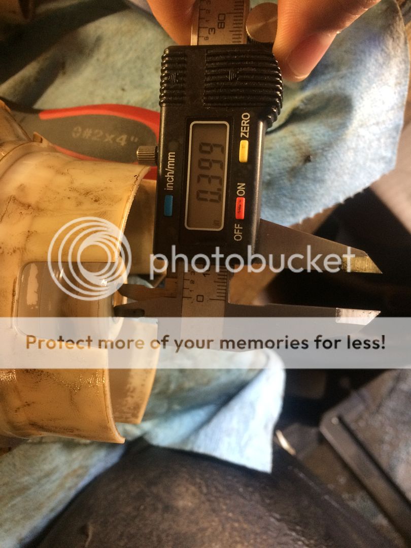
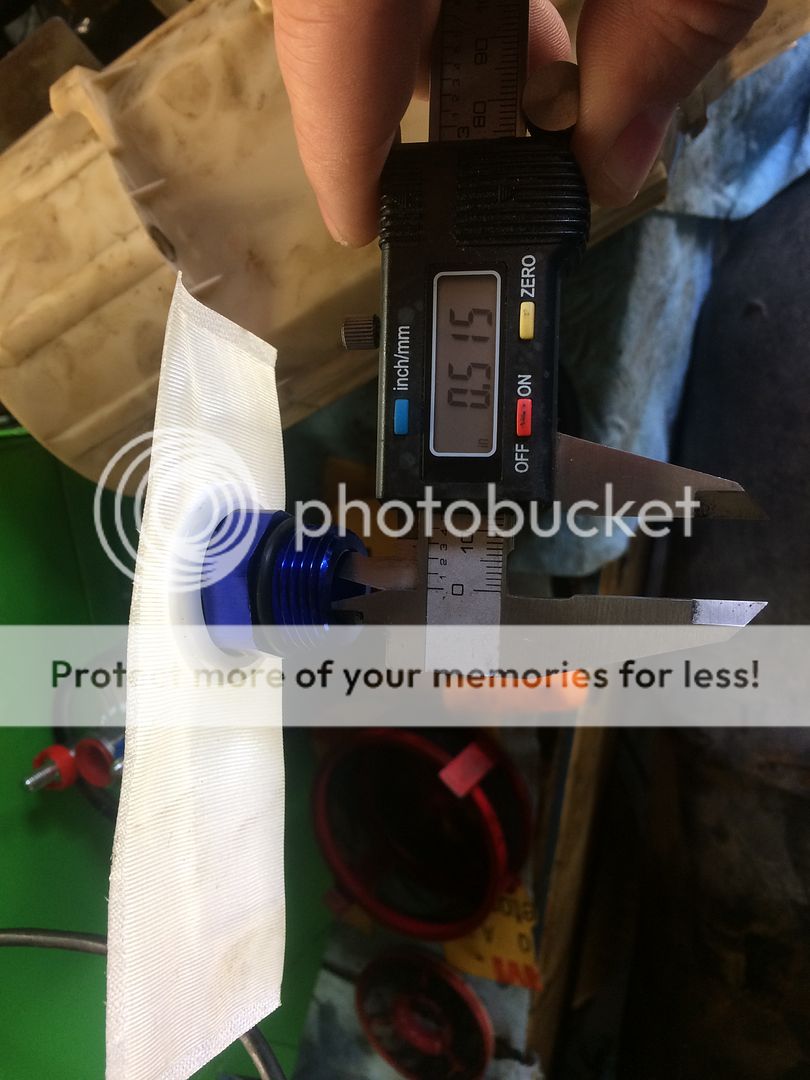
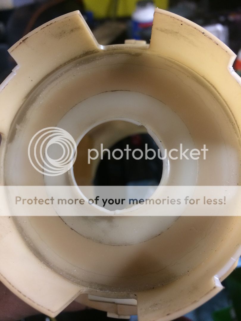
you should have an empty lower half of the sending unit. here are some pictures with the measurement of the inlet size of the sending unit feed and the ID of the inlet screen for the AEM pump.

here are some pictures of the pump i'm using
[ame]http://s5.photobucket.com/user/Temp2/media/1996%20ram%203500/IMG_4250_zpsstt8ffu9.jpg.html[/ame][ame]http://s5.photobucket.com/user/Temp2/media/1996%20ram%203500/IMG_4252_zpszdhbpnuw.jpg.html[/ame]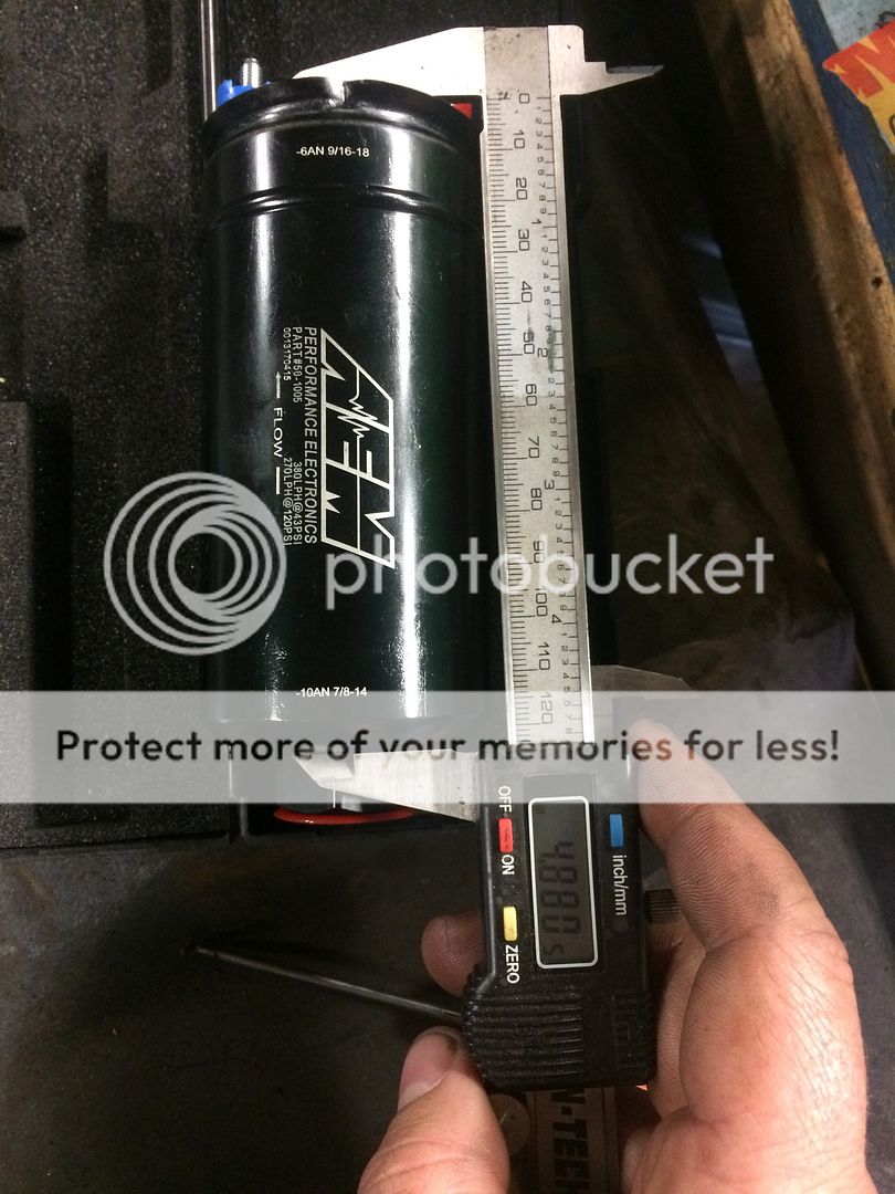 [ame]http://s5.photobucket.com/user/Temp2/media/1996%20ram%203500/IMG_4277_zpsafjzekvi.jpg.html[/ame]
now is the point of no return, use a step bit to open up the bottom hole in the sending unit to just fit the nut for the pickup screen through, but not hex nut on the bottom of the pump body.
I oriented the pickup screen so the long side was facing towards the right side of the truck, so in slosh around left hand turns it would remain more covered, if you want to orientate the pickup screen a different way that's fine, its your truck. cut clearances in the bottom of sending unit "feet" to clear the pickup screen. A fresh razor blade cuts through the plastic material pretty easily.
[ame]http://s5.photobucket.com/user/Temp2/media/1996%20ram%203500/IMG_4288_zpsdevj5fbl.jpg.html[/ame][ame]http://s5.photobucket.com/user/Temp2/media/1996%20ram%203500/IMG_4290_zpsuzj1mf6k.jpg.html[/ame]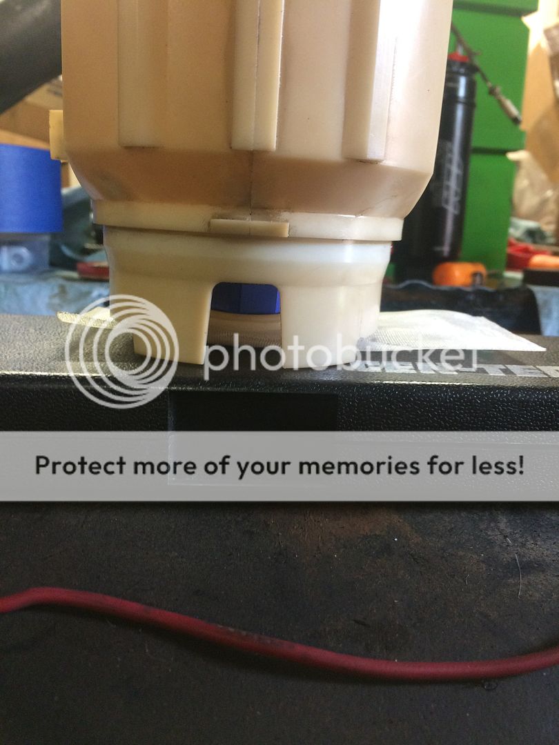
Now, I would assemble the check valve and 8an to 3/8 barb onto the pump now rather than i did later, makes it much easier to tighten everything down than trying to fish a wrench down into the sending unit to snug everything up, you can hold the pickup screen by hand and thread the pump onto the pickup screen. you dont need to tight the pickup screen now, just snug it down to test fit it into the lower section of the sending unit. The pickup screen seals with an Oring, so it doesnt need to be much tighter than hand tight. You should have something similar to this (with the check valve 8an-3/8barb fittings on top). I recommend using some masking tap over the pickup screen and pump outlet to stop getting dirt and other schmoo into the pump/screen/lines.
you'll see that the pickup screen will be drawn up into the pump body a bit, thats perfectly normal and good, you dont want the screen smashed against the bottom of the tank, about 3/8" of clearance from the bottom of the screen fitting to the floor of the tank is really what you want.
[ame]http://s5.photobucket.com/user/Temp2/media/1996%20ram%203500/IMG_4293_zps7ezplvi9.jpg.html[/ame]
now you can test fit the pickup tube retainer over top of the pump. I oriented the pump so one of the body crimps that holds the pump together indexed with the hole for the fuel return tube, helps hold everything in place.
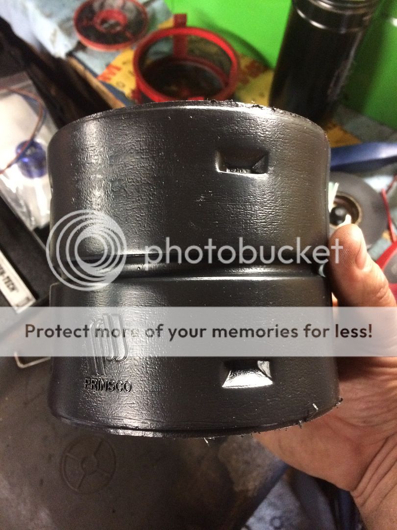
Get the retainer figured out where you want it and take it back out (or dont, i dont care). now its time for the tile drain coupler. I was trying to figure out how i could increase the baffling around the pump pickup. the bottom half of the sending unit acts as a surge tank/reservoir for the pickup (and now pump), but i wanted a little extra around the pickup screen. looking around for some suitable material i was thinking of cutting up a fuel can and using parts of it, the plastic wont damage the inside of the tank like a metal baffle would and wont fall apart like fuel cell foam. i didnt really like the idea of cutting up one of my good fuel cans, so i looked at what material they were made of, high density polyethylene. Did a little more googling for HDPE and found that tile drain tubing and components are made from HDPE, so i went to my local store and looked around for HDPE molded on the side. not all couplers have HDPE on them, some have a ASTM standard number (F667) like mine, but ASTM F667 standard for polyethylene, so its all good.

Let me preface this by saying this is my own experiment, replicated at your own risk and discretion. This modification was done to a 1996 truck, no idea if other sending units vary in design and no guarantee that the pump will fit like mine did if they're different.
I came to diesels from the tuner/hotrod scene and frankly was appalled by the cost and design of some of the aftermarket lift pumps, along with monitoring my factory lift pump (new genuine cummins and gone through the system front to back for cleanliness) pressure at various loads and throttle inputs. my stock truck with the fuel plate removed and some other minor AFC tuning would pull fuel pressure down to nearly 10psi at WOT (adjustable overflow valve idle pressure at 30psi).
So I sat down and had a think about what I needed for my new truck. I have moderate goals for the my new (to me) 1996 dually with 76k original miles 1owner truck, I'd like to make around 400whp (a common goal for many i see on the facebook groups and forums). Many people claim the stock lift pump will do 400hp when shimmed, however i have my doubts after seeing how the pressure responded to my basically stock truck. I also was shocked by the price of the name brand lift pumps (airdog/fass), absurd amount of money for the fuel flow. There has to be a better solution....
Fleece offers a dual pump in tank kit for the 4th gen trucks now, and i believe that is the best solution for them. Why are in-tank pumps the best solution for performance and efficiency? here are some reasons:
1.) No draw straws or sumps. no cutting up your factory tank and losing your factory surge tank/baffle system.
2.) Stock 3/8" fuel line will support alot of power when under pressure. 1000+turbo ls cars are running 3/8" feed line, i doubt a 400-
600hp diesel will need more.
3.) Pump cooling. 90% of what I see in people posting about failed aftermarket lift pumps are from heat. a motor working in
nothing but air needs a ton if air flow and heat sync to keep cool. liquid cools a lot better than a gas does, its why we have liquid
cooled engines and why the OEs have been sticking pumps in the fuel tanks of all vehicles for years
4.) Pump feed pressure (this one is important). your pump is feed by pressure, that pressure is atmospheric pressure pushing on the
liquid. the same way you drink through a straw, you lower the pressure on one side of the hose/tube/straw and the fluid is forced
by atm pressure to the low pressure area. Exactly the same goes for your fuel system.
Ideally external pumps need a very large feed hose, much larger than the output hose because (if they are above the fuel level)
are fed only by a fraction of the ambient air pressure. Only a fraction? Yes, to get full atm pressure (14.7psi at sea level) you'd
need to somehow draw a perfect vacuum (which is basically impossible for a fluid transfer pump). At best, usually they will
create a pressure differential of about only 1-2psi. So how can this be improved? ever do a beer bong? it works because you
not only have atm pressure on the beer, but the WEIGHT of the beer itself pushing itself into your mouth. Same goes for fuel and
your lift pumps. TANGENT WARNING! if you put your external lift pump level or below the tank of fuel and had a sump on the
tank, you could feed it with the fuel column, but nobody is going to hang their $600-1000 fass below the tank level... but I
digress.
So leading back to the in tank fuel pump, the fuel inlet is basically at the bottom of the tank (.250"-.375" off of the bottom
usually), so the full height of the fuel column (fuel above the pump inlet) is working to feed the pump on top of the low pressure
area the pump creates giving superior fuel feed to nearly any external fuel pump system.
5.) Value. Cost is something thats relative to each person, I could have bought a high dollar big name pump setup, but I graduated
highschool at basically the height of the 2008 depression, my frugal parents and life experience has taught me to value money.
Dropping the level of cash on the big name systems just didn't sit well with me for what my needs were and their performance
value. We'll discuss the cost of the lift pump/fuel system setup with each component, but the basic setup could be easily
replicated for about $200-$250.
6.) power, pressure, and flow. stock/mildly modified p7100 pumps have shown to pickup power to about 40-50psi of delivered fuel
pressure. as tested by PDD, fass' "fuel polishing" valve cracks as a overpressure relief around 40psi (the pump is also not
delivering anywhere near the advertised number at that pressure either). The pump I selected delivers the advertised flow at
pressure and has an internal pressure relief valve that opens all the way up 150psi (not that the pump flows much there, but hey
better to have it and not use it right?).
7.) clean installation. no wires or hoses or pumps hanging all over the frame. I found my install to be a very clean/sanitary finished
product and look very OE including using the factory electric fuel pump circuit already built into the truck and harness
That's all I've got for benefits over a "conventional" aftermarket lift pump system...
Basic component list (just to get it going, i'll list the extras later):
Pump: AEM 50-1005, retail on amazon: $151 (https://www.amazon.com/AEM-50-1005-...coding=UTF8&psc=1&refRID=EPSBXTQG4H51SJ5561JD). Read the info on it here (pressure/flow data, amp draw data, etc...) https://www.aemelectronics.com/prod...-fuel-pumps/400lph-inline-high-flow-fuel-pump
inlet filter: AEM 50-200-11, retail on amazon $12.20 (https://www.amazon.com/AEM-50-200-11-Inlet-Filter-Inline-x/dp/B00VBH912E)
8an to 3/8" hose barb: Derale 98201, $4 (https://www.summitracing.com/parts/der-98201)
Tile Drain coupler (you'll see where this comes in later): $2 https://www.menards.com/main/plumbi...-c-9568.htm?tid=-7042517412670233045&&ipos=33
Misc screws, hose, and clamps $20-free99 depending on what you already have and your resources.
So first thing you need to do obviously is remove the tank and sending unit. I despise the factory nylon tubing they started using in the early 90s on everything for fuel line, you can keep it but I personally always remove it and replace it with high pressure rubber hose and clamps. easy way to remove it from fittings/tubing is cut it length wise along fitting/tubing. releases the tension and easily comes off. You do need to save the quick connect fittings on the tank however if you are going to keep the install as clean as possible.
heres cutting the nylon lines

once you have the fuel sending unit out you can start disassembling it. first thing should be the three screws holding the top to the bottom half, go ahead and cut the fuel line that goes to the center pickup tube and disconnect the two spade connectors on the fuel level sensor !!BE EXTREMELY GENTLE WITH THE LEVEL SENSOR, I WAS NOT AND NOW HAVE TO TAKE THE TANK BACK OUT OF THE TRUCK TO FIX IT!!! the other two hoses going down into and along side the sending unit should just slide out with the top of the sending unit, leave these attached.
here's a picture of the level sensor and two wires

set the top of the sending unit aside for now, remove the level sensor from the side of the lower half of the sending unit (two screws) and set aside, remove pickup tube retainer, pickup tube, fuel return screen, fuel feed screen and fuel feed check valve/float (just pulls out from the bottom)
pickup tube retainer

pickup tube
[ame]http://s5.photobucket.com/user/Temp2/media/1996%20ram%203500/IMG_4269_zpskx1gbwhe.jpg.html[/ame]
you should have an empty lower half of the sending unit. here are some pictures with the measurement of the inlet size of the sending unit feed and the ID of the inlet screen for the AEM pump.


here are some pictures of the pump i'm using
[ame]http://s5.photobucket.com/user/Temp2/media/1996%20ram%203500/IMG_4250_zpsstt8ffu9.jpg.html[/ame][ame]http://s5.photobucket.com/user/Temp2/media/1996%20ram%203500/IMG_4252_zpszdhbpnuw.jpg.html[/ame]
 [ame]http://s5.photobucket.com/user/Temp2/media/1996%20ram%203500/IMG_4277_zpsafjzekvi.jpg.html[/ame]
now is the point of no return, use a step bit to open up the bottom hole in the sending unit to just fit the nut for the pickup screen through, but not hex nut on the bottom of the pump body.

I oriented the pickup screen so the long side was facing towards the right side of the truck, so in slosh around left hand turns it would remain more covered, if you want to orientate the pickup screen a different way that's fine, its your truck. cut clearances in the bottom of sending unit "feet" to clear the pickup screen. A fresh razor blade cuts through the plastic material pretty easily.
[ame]http://s5.photobucket.com/user/Temp2/media/1996%20ram%203500/IMG_4288_zpsdevj5fbl.jpg.html[/ame][ame]http://s5.photobucket.com/user/Temp2/media/1996%20ram%203500/IMG_4290_zpsuzj1mf6k.jpg.html[/ame]

Now, I would assemble the check valve and 8an to 3/8 barb onto the pump now rather than i did later, makes it much easier to tighten everything down than trying to fish a wrench down into the sending unit to snug everything up, you can hold the pickup screen by hand and thread the pump onto the pickup screen. you dont need to tight the pickup screen now, just snug it down to test fit it into the lower section of the sending unit. The pickup screen seals with an Oring, so it doesnt need to be much tighter than hand tight. You should have something similar to this (with the check valve 8an-3/8barb fittings on top). I recommend using some masking tap over the pickup screen and pump outlet to stop getting dirt and other schmoo into the pump/screen/lines.

you'll see that the pickup screen will be drawn up into the pump body a bit, thats perfectly normal and good, you dont want the screen smashed against the bottom of the tank, about 3/8" of clearance from the bottom of the screen fitting to the floor of the tank is really what you want.
[ame]http://s5.photobucket.com/user/Temp2/media/1996%20ram%203500/IMG_4293_zps7ezplvi9.jpg.html[/ame]
now you can test fit the pickup tube retainer over top of the pump. I oriented the pump so one of the body crimps that holds the pump together indexed with the hole for the fuel return tube, helps hold everything in place.

Get the retainer figured out where you want it and take it back out (or dont, i dont care). now its time for the tile drain coupler. I was trying to figure out how i could increase the baffling around the pump pickup. the bottom half of the sending unit acts as a surge tank/reservoir for the pickup (and now pump), but i wanted a little extra around the pickup screen. looking around for some suitable material i was thinking of cutting up a fuel can and using parts of it, the plastic wont damage the inside of the tank like a metal baffle would and wont fall apart like fuel cell foam. i didnt really like the idea of cutting up one of my good fuel cans, so i looked at what material they were made of, high density polyethylene. Did a little more googling for HDPE and found that tile drain tubing and components are made from HDPE, so i went to my local store and looked around for HDPE molded on the side. not all couplers have HDPE on them, some have a ASTM standard number (F667) like mine, but ASTM F667 standard for polyethylene, so its all good.


Last edited:


