Smokem
Turbler
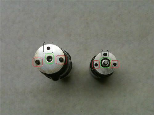
Marker - part name
Black - shim
Red - compression spring
Green - compression pin
Blue - intermediate disk
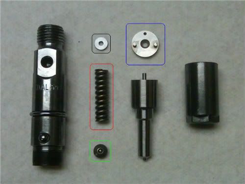
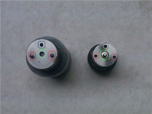
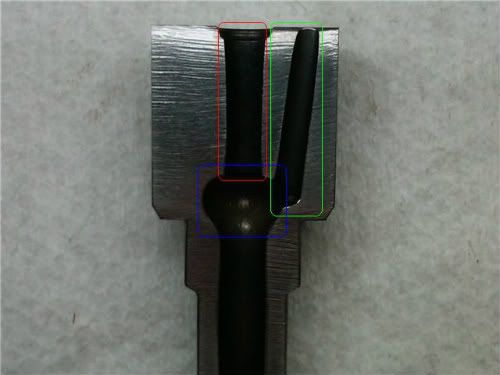
Marker - part name
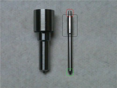
Black - feed passage
Red - alignment pins
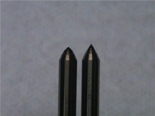
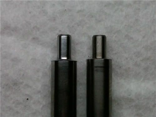
Green - pin opening/pintle
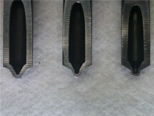
Marker - part name
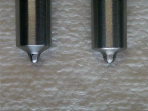
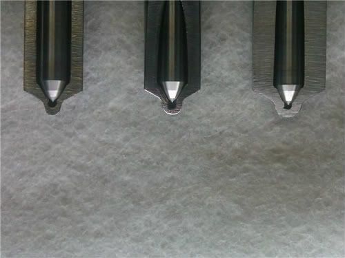
Black - pintle seat
Red - sac/blind-hole
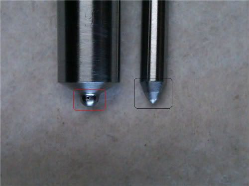
Sac nozzle with cylindrical blind-hole.
Marker - part name
Black - pintle seat
Red - sac/blind-hole
Sac nozzle with micro blind-hole.
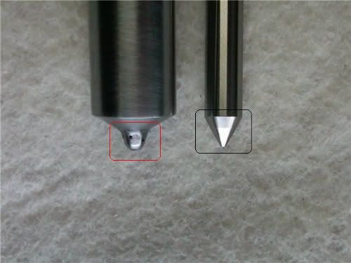
Marker - part name
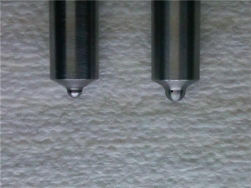
Black - pintle seat
Red - nozzle tip
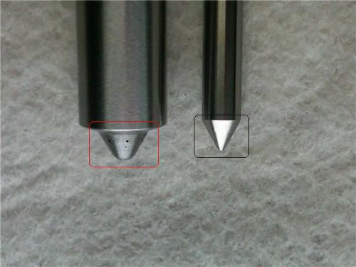
VCO nozzle.
Marker - part name
Red - needle guide
Green - feed passage
Blue - fuel gallery
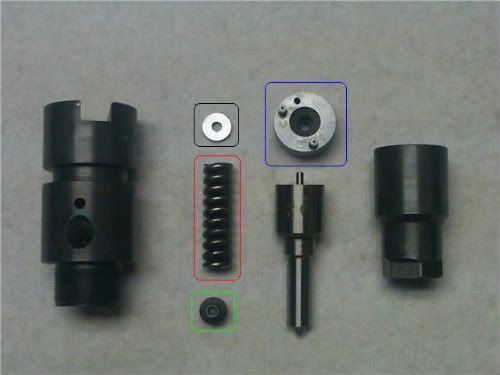
Black - shim
Red - compression spring
Green - compression pin
Blue - intermediate disk
Marker - part name
Black - feed passage
Red - alignment pins
Green - pin opening/pintle
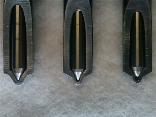
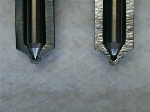
Marker - part name
Black - pintle seat
Red - sac/blind-hole
Sac nozzle with cylindrical blind-hole.
Marker - part name
Black - pintle seat
Red - sac/blind-hole
Sac nozzle with micro blind-hole.
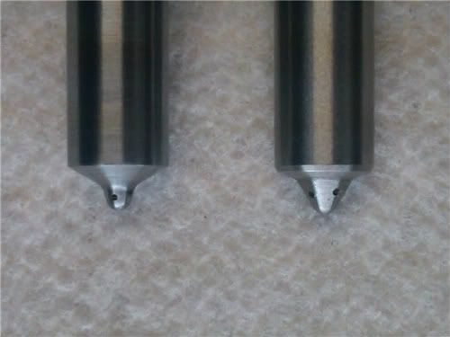
Marker - part name
Black - pintle seat
Red - nozzle tip
VCO nozzle.
Marker - part name
Red - needle guide
Green - feed passage
Blue - fuel gallery
Last edited by a moderator: