FordCummins/DCS Tach Kit

jcarrick

New member
Joined
Nov 7, 2012
Messages
137
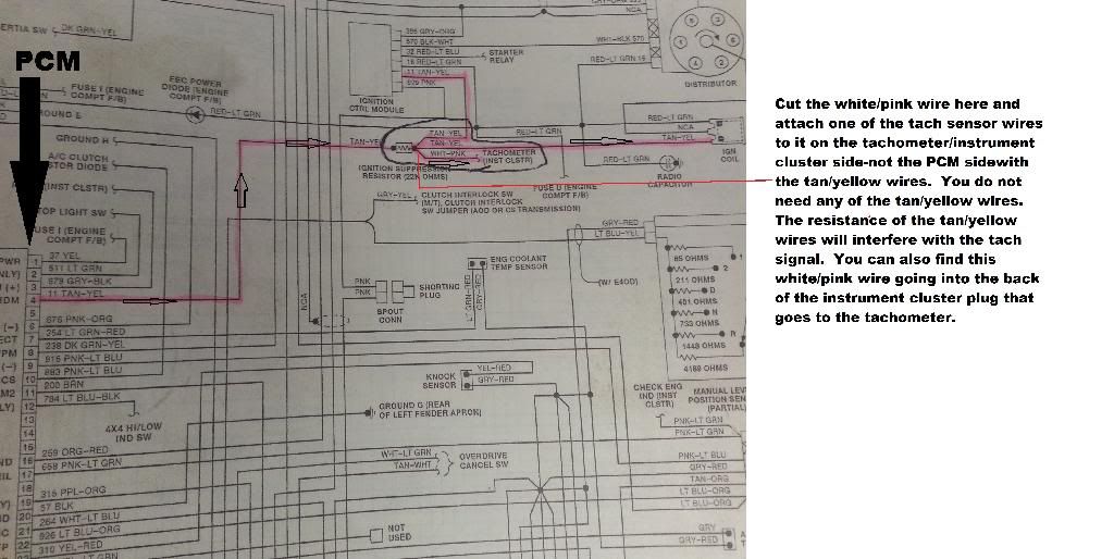
Has anyone been able to get one of these hooked up and working? I am trying to install one in my 1997 F350 that originally had the 460 but i have had zero luck with making it work. They told me to grind two more notches into the balancer, which i did, and then wire one wire to ground and the other to the "wht/pnk" wire. I tried that again tonight and still have no luck!! I called them for the 3rd or 4th time about it and every time they tell me the tech will call me back, but that has never happened. Can anyone enlighten me on how they got this wired or how i need to wire it in my pickup?

Thanks

-Jon
 
where did you tap into that wht/pnk wire, I haven't gotten mine to work yet, but someone said I needed to hook right by the cruise control servo by the drivers side fender. It would be great if these companies that demand huge money for parts could just give some actual tech support.
 
I think that's where I tried hooking it up. Right at the ecu plug. But still nothing. Ya, you would think if you developed a sensor you would know how to wire it, but I guess that's too much to ask, haha.


Sent from my iPhone using Tapatalk
 
Jcarrick, I do the tech support for DCS. Sorry about the confusion on the tach sensor but we’ll get you taken care of. We always encourage feedback, and are reviewing the manuals to better explain/clarify the tach procedure. The white/pink wire is near the coil, and is attached to the tan yellow wires that go to the coil on your 460. Make sure that you remove the tan/yellow wires, as they can cause interference with the tach signal. The gap is very important to the sensor producing a signal as well. Make sure that you have removed the O-ring from the sensor, if it had one, and screw the sensor tight to the L bracket. Then set your gap at 18-20 thousandths. If you have any other questions, please call me or email me at ds@dieselconversion dot com.
 
Thank you for the info and the call back this morning. I will remove the o ring tonight and once I get that schematic from you I will wire it in and go from there. I appreciate the help and hopefully we can get this thing reading some rpms soon


Sent from my iPhone using Tapatalk
 
please share that schematic. I think I have mine tapped into that tn/yl wire right now, thanks duey for clarifying.
 
Hopefully Duey can post it in the thread today. I didn't get an email yesterday a


Sent from my iPhone using Tapatalk
 
Sorry guys. I was out of the office on friday. I have the schematics at work. I will get back to you on monday and can explain them. You cam pm me your email fummins 97 and jcarrick so I can better help.
 
I got your messages. I replied to your email addresses, with my contact information, and a pictured schematic. Please call me if you need more help with this, and we can discuss it over the phone better.
 
If you could post the schematic, I'm facing this issue as well.

Email sent in PM.

Thanks!! Eric
 
Jcarrick, I do the tech support for DCS. Sorry about the confusion on the tach sensor but we’ll get you taken care of. We always encourage feedback, and are reviewing the manuals to better explain/clarify the tach procedure. The white/pink wire is near the coil, and is attached to the tan yellow wires that go to the coil on your 460. Make sure that you remove the tan/yellow wires, as they can cause interference with the tach signal. The gap is very important to the sensor producing a signal as well. Make sure that you have removed the O-ring from the sensor, if it had one, and screw the sensor tight to the L bracket. Then set your gap at 18-20 thousandths. If you have any other questions, please call me or email me at ds@dieselconversion dot com.

While you're around here, what can you do for a truck that had a 4.9 L6 in it before as far as hooking up the tach? I called y'all a couple of years back to order parts, and whoever it was I was talking to said he didn't know for sure if/how they could do it, and that someone would call me back. Been two years and still nothing LOL
 
hooked mine up with the green wire with yellow strip, come from a red connector on driver fender. That's for a 89 460efi
 
Thanks for the diagram Duey!

Heres what Duey sent me today. I havent gotten to test it out yet, but hopefully it works:

0B83BA33-B23C-40FD-99AF-66942B698B81_zpsvkcgar8i.jpg
 
He also told me to be sure to remove the rubber o-ring on the sensor before screwing it into the bracket and set the gap at .014-.020. I will put this together later this week and see if it works.
 
I finally got the tach working and its awesome! Heres a quick pic:

9CA12ED3-4A2D-47F7-B2CA-C2A2B2D4AEEB_zpszu44xbvi.jpg


Heres a short write up of how to make it all work:

First off, take the rubber o-ring off the sensor. When you get it mounted set the gap at .014. I've heard, between .010-.020, but .014 works great. From here it doesn't matter which wire you ground or send to the tach. The best way to get a good signal is to run the signal wire straight up to tach gauge. To do this you need to pull the gauge cluster. Heres a quick youtube video i found on that: [ame="http://www.youtube.com/watch?v=WsN5owpxCXQ"]http://www.youtube.com/watch?v=WsN5owpxCXQ[/ame]. Next, find the white and pink wire that is in the connector right behind the tach. Cut it and connect the signal from the sensor to the wire going into the cluster. I did not reconnect the other end of the white and pink wire because i didnt think it was necessary. I will find out if it needs this when i hookup the ac or a remote start or something, but for now it works great. The other wire from the sensor just gets grounded.

I really hope this helps everyone get their tachs hooked up as well and if anyone has anymore info to add it would be awesome to compile it all in this thread!

-Jon
 
Back
Top