Converter Lock Up

zukgod1

Old fart
Joined
Jul 18, 2006
Messages
1,397
Yes I did a search, and no I'm not looking for TST's diagram.

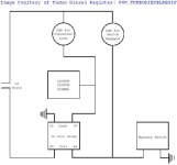
Before we all come to comp I remember seeing a set up someone designed that consisted of I think 4 relays.
It was designed with a switch in the circuit still.

If switch was in the lock position and you forgot to turn it off when you hit your brakes it would unlock the converter, you would then need to reset the circuit by turning the switch of and back on.

Anyway, I want to install a lock up switch but I dont want to hard wire it,
there was a link or post somewhere to this set up.
Anyone remember what I'm talking about
Have linky?

dan
 
What is required for the lock up switch to work? 12V positive? If that is what is needed I can work out a schematic for that, just lemme talk to one of the guys at work to make sure I have my thinking right on how to do it.

That or Jory can just step in and tell us both how LOL LOL
 
Billysgoat said:
What is required for the lock up switch to work? 12V positive? If that is what is needed I can work out a schematic for that, just lemme talk to one of the guys at work to make sure I have my thinking right on how to do it.

That or Jory can just step in and tell us both how LOL LOL


You have to complete the ground on pin # ? to achive TC lockup in 2-4. i usually just use a toggle switch that is grounded and runa pin out to the other end. But it would be nice of it worked like BD's old setup.
 
Billysgoat said:
What is required for the lock up switch to work? 12V positive? If that is what is needed I can work out a schematic for that, just lemme talk to one of the guys at work to make sure I have my thinking right on how to do it.

That or Jory can just step in and tell us both how LOL LOL


Like supersonic said it a ground.

You can just tap the TC wire where it goes in the PCM and run it in the cab hook it to one side of a toggle switch and the other terminal on the switch to a ground on the chassis.


The diagram I remember seeing used the brake lite as a trip wire and a 12v to power the relays. I cant remember exactly how it was wired is the problem.
It was set up so when you flipped the toggle switch (I think it was a momentary on toggle) it would charge a relay grounding the wire and locking the TC. The brake lite reference was use to brake the circuit if you hit the brakes.

Does that make sense?

I had the damn thing printed and saved in a file just in case and I think I tossed the whole file when I sold the truck.

Can you do something with that?

dan
 
SHE BANG!!!!!!!!!!!!!!!!!!!!!!!!!

Found it!!!


dan


Edit: Image removed at poster's request
BG
 
Last edited by a moderator:
Would this work? http://suncoastconverters.com/dodge/dodge_products.html


Loc-Up Installation Sheet


If you need assistance installing or programing your controller, you can start by downloading this pdf instruction sheet for review.


Sun Coast Loc-UpController


1994-03 Part No. PL-TCC-TOW


Part No. PL-TCC-RACE


Race version has an extra 4th gear control.


Any vehicle using an exhaust brake with automatic transmission will benefit from the installation of a Sun Coast Loc-Up Torque Controller.
The Sun Coast Loc-Up Controller gives you the option of programming Torque Converter Clutch (TCC) engagement and release speeds, or allowing factory computer strategy control.
Most factory computers release the TCC on lift throttle. With or without an exhaust brake this strategy reduces the effectiveness of engine compression braking. When the TCC is in the release mode it no longer has a mechanical connection to engine rotation. When in the disconnect mode the torque converter produces an enormous amount of heat with little or no engine braking.
Many factory strategies do not allow TCC engagement until very high road speeds. Many times this higher setting inhibits vehicle performance and fuel economy.
The Sun Coast Loc-Up Controller allows the operator to choose when the TCC engages or releases. This results in:


Reduction of transmission and torque converter operating temperatures.


Reduce wear and overheating of brakes.


Improved acceleration and fuel economy.


Program any speed you wish to lock. Program any speed you wish to unlock.

 
Last edited:
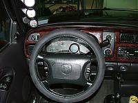
Here's my two LED setup. The yellow LED will turn on whenever the PCM or I manually give the signal. My red LED will turn on when I throw the L/U switch, reminding me "Red is bad, turn me off before you come to a stop" :bang

You can see my LEDs in this pic right above my shifter.
 

Attachments

  • lock-up%20relay.jpg
    lock-up%20relay.jpg
    20.4 KB · Views: 39
  • 2006_0221%28004%29.jpg
    2006_0221%28004%29.jpg
    8.6 KB · Views: 46
Burner said:
Would this work?

Sure, that would work.

If you wanted to spend $400+. :poke:

The one I posted can be built for less than $50.00.
Sure it's no programable but I can flip a toggle switch a hella times for the extra $350.00


dan
 
I still have a issue though, if I lock the converter with the wire attached to the PCM it's going to set off a code, prob TCC solenoid failure or something like that.

I need to cut that wire and run it through a resistor or something to prevent back feed to the PCM.
So the Diagram above will run the lock up yes but it will not prevent a Service engine light.

What if I was to run the wire from the PCM to the "Lock" side of the toggle switch? that would still lock the converter when the PCM called for it and not backfeed to the PCM when it was locked..??


Any suggestions?

dan
 
Last edited:
The more I analize this diagram the more I think it's missing something.

Like an external ground, without it where is the signal comming from you are supose to be sending to the converter solinoid?

Also I wonder if I need to remove and jumper where the Trans relay is on the panel..??

dan
 
Last edited:
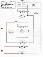
This Is The Correct Diagram!!

The one posted above is incorrect!

I will get Billy or someone to pull it down ASAP.
The correct one is here, hope no one tried what I did and found it doesnt work.

We still need to figure out how to keep the SEL light from comming on.

NOTICE!!
I added the leg where it says "To PCM", we need a signal comming from the PCM to charge the system thus locking the converter. I need someone with a background in elec eng to tell us what kind of resistor etc we can us inline on this wire to make sure we donr get feedback through it setting of the SEL.

dan
 

Attachments

  • 204993_relay_mystery_switch_directions_001.jpg
    204993_relay_mystery_switch_directions_001.jpg
    32.8 KB · Views: 24
I know this posting is kinda old but I was wonder what that square at the bottom on the last image was in the diagram?
 
that makes sense, thanks and also I know a little bit about diodes but what kind do I put in that location, thanks again
 
Back
Top