Bosshawg600
PDP.com FireFighter
- Joined
- Aug 3, 2006
- Messages
- 3,651
Ok so the motor is starting to go together now. But I ran into a little problem.
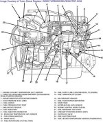
First off, I cant figure out my oil lines to the p-pump. I got the line comming from the back of the pump and the T'ing at the block....but where does it go from there? Back into the block? I dont see anywhere that it goes back to the pump. Any one got a schematic of the P-pump oil feed?
Second, I cant exactly remember which sensor goes where on the head. Got another electrical diagram of that?
Looks through about everything I can, just want to get it all right while the motor is out and not have to mess with it once the motor is in.

