F250/Cummins Swap

30 miles east of Glasgow!
I just bought a pickup from a guy in Gradyville a couple months ago
I'm about 35 miles north west of Elizabethtown.
Sold the 6.0 shroud with the radiator, using a 7.3 radiator and shroud with a 2nd gen fan.
 
I got all upset about my dog and cut a brand new dodge lower rad hose too short. Atleast they look good.
01be9519ddfcebbb02d28b2d2bfad6e7.jpg


Sent from my XT1575 using Tapatalk
 
30 miles east of Glasgow!
I just bought a pickup from a guy in Gradyville a couple months ago
I'm about 35 miles north west of Elizabethtown.
Sold the 6.0 shroud with the radiator, using a 7.3 radiator and shroud with a 2nd gen fan.

Harned, huh?
My wife lived at Sample when she was a little girl, and we’ll be in Payneville for a friends wedding tomorrow.......
Small world.
 
Have several friends in Sample, may know her.
Payneville isn't very far, I'll be working on a sawmill in Webster tomorrow.
Had to replace a 150 hp electric motor today, 4.0 wire is a pain to work with.
Tomorrow I'll be trying to figure out why a 60 hp hydro static drive won't maintain charge pressure, plus making a list of electrical components we'll need to power up the new edger that came in Monday.

If you have time give me a shout, I'll show you my Fummins work truck.
270 nine four 5 fifty five 51
Names John
 
Back on track.

Transfer case input swap in progress.

The dodge input shaft has the interior bearing 10mm deeper than the Ford. I took measurements and then popped the new shaft in the press to adjust it.

Pictures when I have service

Sent from my XT1575 using Tapatalk
 
NP273F on the left, NP273D 23 spline on the right.
dae39661785f2a126aee7fd493d9588b.jpg


So the pocket bearing depth on the 273D needs to be adjusted. The D is 10mm deeper that the F, and it won't support the end of the main shaft at 10mm.
I used my GP 19mm extra deep socket, and a socket large enough to safely press the input shaft to adjust the bearing and cup plug.
705e40c8b078cadd5b5eeef04b606ff3.jpg

d7baf5a618df7ee9a561eda8acbab401.jpg

741d173db918db66800a3cfb0387be61.jpg
 
Last edited:
I didn't take disassembly pictures, but I tried to get a few during assembly, so I'm going to post them in reverse.

Pull the drive flanges. I used a 3 jaw otc puller. Nuts were metric. I used 1 1/8" and 1 1/2" sockets to pull the retaining nuts.
ccc5309c7d23945470eb644e3f600662.jpg

Remove the input seal. Remove the snap ring from the input shaft. Use snap ring spreaders. Life is too short to dick around with snap rings.

37d168634f00e880bb6717a2f96002a9.jpg

Pull the 13mm bolts that hold the (input housing?) and set it aside. You can see the oil pump at this point.
The oil pump has a plastic sump that indexes the pump. Take a flat screwdriver or needle nose pliers and pull directly outward on the sump tube. Remove the pump.

089e7b2b68ab84f1aabb5aaa5a6166b7.jpg


You can remove two snap rings and slide the chain and sprockets off their respective shafts.
5b2b1574a08d5f4f458caa4cc260bd0c.jpg
6d0e329295dcc128bc76515d3fae5563.jpg


I didn't take a good picture of the main shaft, but you can give it a stern yank and it will come out of the clutch assembly and input shaft.
db528659336db9434ee202c83c6056f2.jpg
671f4716ede231acd7c3806df9b46083.jpg
868e8d7c6eeb62d0afea8cc053fb5a1c.jpg
0dfb9f2af061601cb9c1147cd5042d30.jpg


Sent from my XT1575 using Tapatalk
 
Last edited:
I ran out of time to edit.

After you pull the outer fork, the common shaft for the forks should slide out. You can slide the interior fork up out of the planetary, an simultaneously disengage the fork from the cam plate.

At that point, you can remove the planetary and input shaft.
6b63b6ed0636249b5616d8ec7e0bc9ad.jpg


Sent from my XT1575 using Tapatalk
 
There is an internal snap ring retaining the input shaft. There are also some friction type washers to keep track of.
ebc93df8f8a61fd2de66a4ba5cbe27bb.jpg


Swap in your adjusted pocket bearing 23 spline input shaft and start working backwards.

I got ahead of myself and put the input seal in before I installed the snap ring in the input shaft. I took it all apart and carefully removed the seal from the inside.

The only two notes I have for assembly are
1) fully seat the sump into the side of the pump
2) be careful to get the shift fork rod into the pockets in the front and rear housings. The housings should mate almost completely together with little or no force.
3) it isn't necessary to remove the drive flange for the front drive shaft to swap inputs.
Sent from my XT1575 using Tapatalk
 
Last edited:
Is anyone running the air filters from vibrant performance to give any feedback?


Sent from my XT1575 using Tapatalk
 
Didn't know anything about Vibrant so I looked them up.
Filters look like the AFE filter I used to have but they don't show one of any decent size.
Also seen a note saying the filters are not intended for forced induction apps.
Turbo's are forced induction!
 
Well... I'm not a welder. But when I do, I like to forget to turn the feed down. So I blew two holes in my exhaust while trying to tack on hangers.

They will be fixed when the hangers are finish welded.

The flanged pipe that connects to the 6.4 downpipe is going to work well with the SD downpipe I put on, in terms of clearing the Trans crossmember.

I relocated one of the Ford exhaust hangers. The Ford frame has holes everywhere for exhaust hangers. I'm also going to cut and move the forward more hanger to have it engage the exhaust hanger on the 96 dodge transmission mount.

Cutting the downpipe to correct it, cutting and "bumping" the first section of exhaust, and then cutting and rewelding the axle hump hangers are the biggest modifications needed.

And I either lost my HX40 clamp or someone took it.
e50228c87bee86b8f89e6b910fe9c566.jpg
5c7a4fb5e8f572948df195b0a59bdecb.jpg
5c51c0b45e4f46a8623fd233653c94e6.jpg
4d8f2a8821876c1002f24e7a9087982a.jpg
3bad3b55e5607ead03d4282455c9d4fc.jpg
d57705bca7d13b5aef207631a1213a23.jpg
873e68997259d68cd24e71d86b1d0035.jpg
a0d25847d217bb9489143fe2e9df01b2.jpg
d42faa8b8f62be420467771c35c0117f.jpg


Sent from my XT1575 using Tapatalk
 
I didn't catch that note. Thank you for pointing that out.
Didn't know anything about Vibrant so I looked them up.
Filters look like the AFE filter I used to have but they don't show one of any decent size.
Also seen a note saying the filters are not intended for forced induction apps.
Turbo's are forced induction!

Sent from my XT1575 using Tapatalk
 
MBRP makes a 4" in straight cut but everything I found with 5" in where angle cut.

I used the 6.0's down pipe by cutting and turning it 90 degrees, welded a hx40 flange to the 6.0's bell.

DSC00476.jpg


I'm running a smaller exhaust than you with 3" down and 4" back.
 
JAMO came with a tip. It was encased in expanding foam on the bottom of the box.


Transfer case is in. I need a transmission mount that is 1/2" shorter than the 96 dodge mount. The Tcase hit floor of the cab.

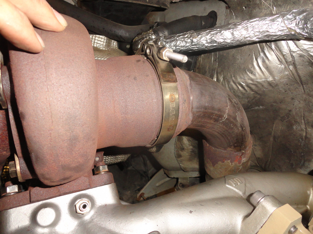
The "bumped" pipe from the 6.4 jamo kit with the flange cut off worked perfectly. I pulled all of the exhaust back off to finalize some bracket/hanger relocation but it's otherwise done.

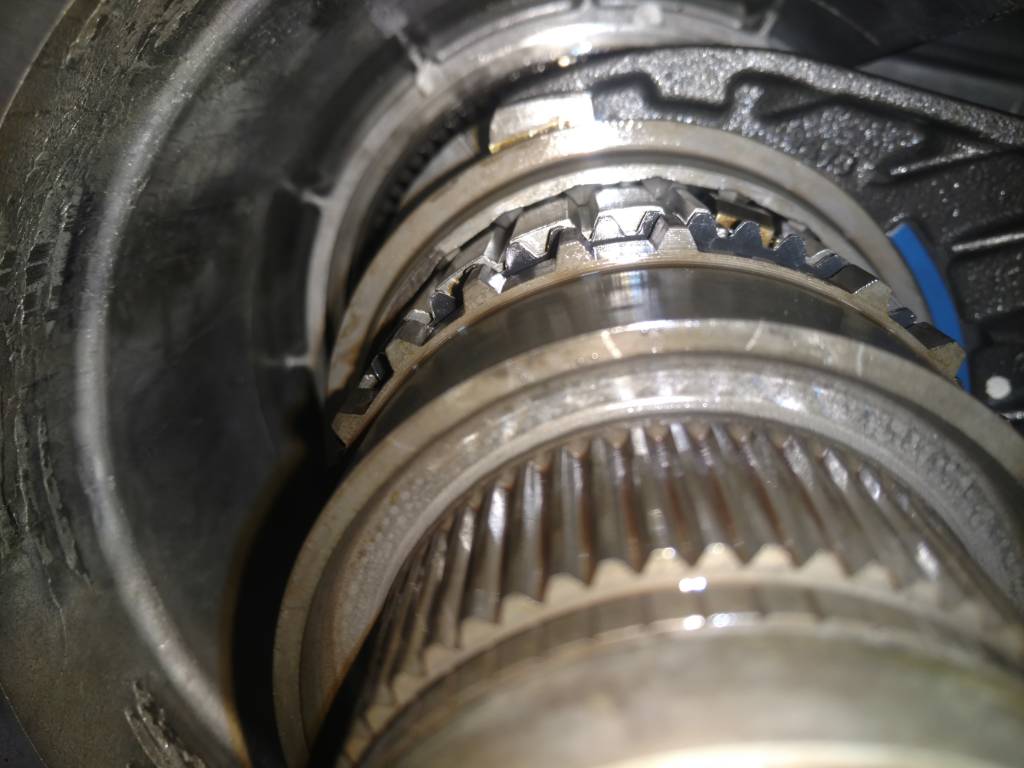
The rear driveshaft bolts in with no modification. It came up 1/4" short of the flange at the Tcase. I loosened the carrier mount and bolted it all up.

The concern now will be the final resting place of the radiator and fan shroud.

Which brings me to my next topic:
I was trying to get away without buying the 6.4 radiator (yet).

With the 5.4 rad in, the 6.4 shroud won't get anywhere near where it needs to be, so the engine is still not bolted down.

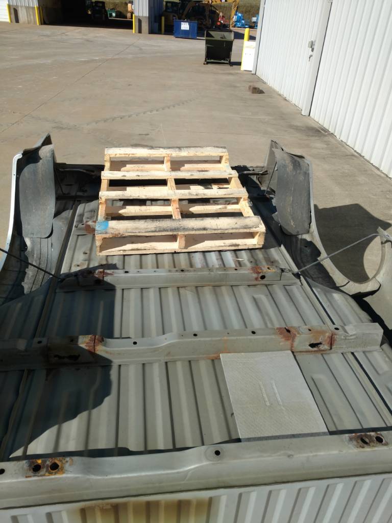
Lastly is the bed. I pulled it so I can to surgery. I went with the APDTY (I think?) kit. I found a place in TN that had it listed on Amazon for $100 less than anyone else I looked at.
ed050960a3d4b3d8e4ca194856b1d170.jpg
9eedfa9979a837fa87edf0dc1a4a5e57.jpg
306140edb03d40401e3e4214006c8d54.jpg
cc0c7b41a1b00e4a512cc0a333cf0a2d.jpg
f54b89b2f3c6c89b56161b56edf30660.jpg
434127005fdc6c18743c2654084e508c.jpg
 
Last edited:
Back
Top