You are using an out of date browser. It may not display this or other websites correctly.
You should upgrade or use an alternative browser.
You should upgrade or use an alternative browser.
ECM Programmers ?? and Secret Squirrel Chit
- Thread starter 4x4dually
- Start date
4x4dually
Moderator
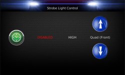
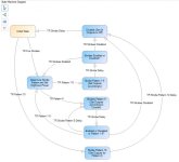
'Cause its fixing to get real. Programming it to control my really old NOV-460 strobe power supply. ")
Will be pattern selectable for Quad, Mega, Quintuple, and Double flash and be front/rear/all selectable as well as high or low power. I'm also going to program it to do "random" which will cycle through all the patterns. The Timer button will give a short quad flash on the front only for 2 second....for those instances where I either want to say "hi" or say "GTFOML!"

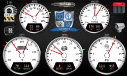
Updated main screen.

Will be pattern selectable for Quad, Mega, Quintuple, and Double flash and be front/rear/all selectable as well as high or low power. I'm also going to program it to do "random" which will cycle through all the patterns. The Timer button will give a short quad flash on the front only for 2 second....for those instances where I either want to say "hi" or say "GTFOML!"
Updated main screen.
Attachments
Last edited:
4x4dually
Moderator
Mad, maybe. Crazy, yes. LOL
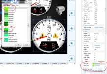
I was also hoping to get some more exposure to the new member in hopes that someone could tell me more about what parameters are buried in all the data blocks that I'm tossing out when parsing out the engine data. I'm throwing away more data than I'm keeping at this point but there is no way to tell what data is in there. Any new folks got access to that $5000 subscription to Chrysler's proprietary bull crap?
I was also hoping to get some more exposure to the new member in hopes that someone could tell me more about what parameters are buried in all the data blocks that I'm tossing out when parsing out the engine data. I'm throwing away more data than I'm keeping at this point but there is no way to tell what data is in there. Any new folks got access to that $5000 subscription to Chrysler's proprietary bull crap?
4x4dually
Moderator
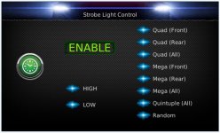
Well, that aught to about do it for the blinky light subroutine.

What I ended up with for a control screen. The little blue lights next to the text will only show up on the selected ones on the display. They are set to show all on the config tool so they are all on in the pic.

Now....to get the truck in the shop and pull a few hundred feet of wire......
What I ended up with for a control screen. The little blue lights next to the text will only show up on the selected ones on the display. They are set to show all on the config tool so they are all on in the pic.
Now....to get the truck in the shop and pull a few hundred feet of wire......
Attachments
4x4dually
Moderator
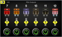
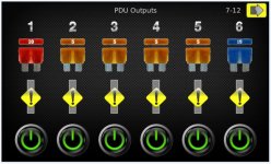
Starting to program the PDU diagnostic page. The PDU is a separate module that will mount outside the cab and control the strobe pack as well as any other device I want to add. Probably just lights mostly. It is connected to the display via the CAN bus.
The PDU is programmable to set fuse limits (soft fuses) and read back current on each channel. This page will show the soft fuse size for each channel (fancy little fuse icons I googled and modified) as well as the current in a bar graph under each fuse of the actual current being used by each channel. The little warning triangles will show up if the current exceeds the soft fuse setting and shuts the channel down. I can also manually turn each channel on and off with the power button if I want to trouble shoot each channel individually. Most all of the channels will be controlled by functions on other screens.
First draft. And yes, I made a fuse icon for every ATC fuse size from 1 to 40.
Attachments
4x4dually
Moderator
4x4dually
Moderator
Yip. Not even using outputs 7-12 yet...but just in the name of 'cause. LOL
Outputs are programmed in 2.5 volt increments so I made all the fuses the correct color and then changed the 1,2,3, and 4 amp versions to 2.5, 12.5, 17.5, and 22.5 so I would at least have a different color for each setting. At least most of them have the correct colors.

Outputs are programmed in 2.5 volt increments so I made all the fuses the correct color and then changed the 1,2,3, and 4 amp versions to 2.5, 12.5, 17.5, and 22.5 so I would at least have a different color for each setting. At least most of them have the correct colors.