BC847
New member
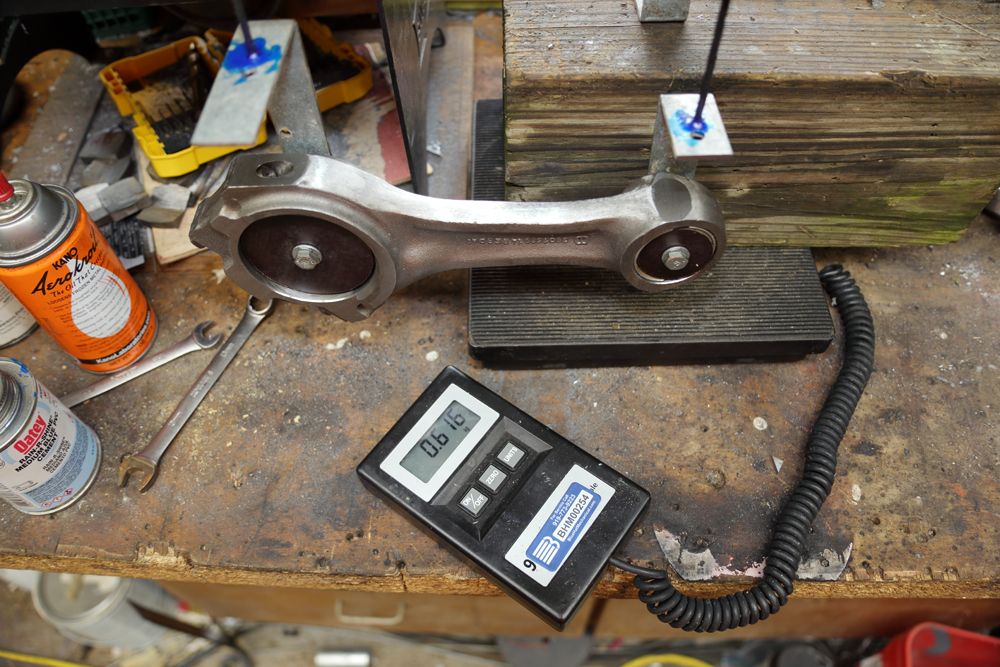
I remember that thread: Crank lightening - Competition Diesel.Com - Bringing The BEST Together
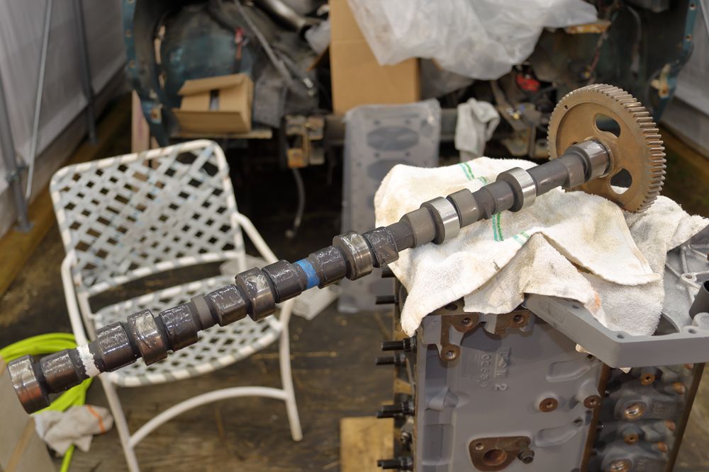
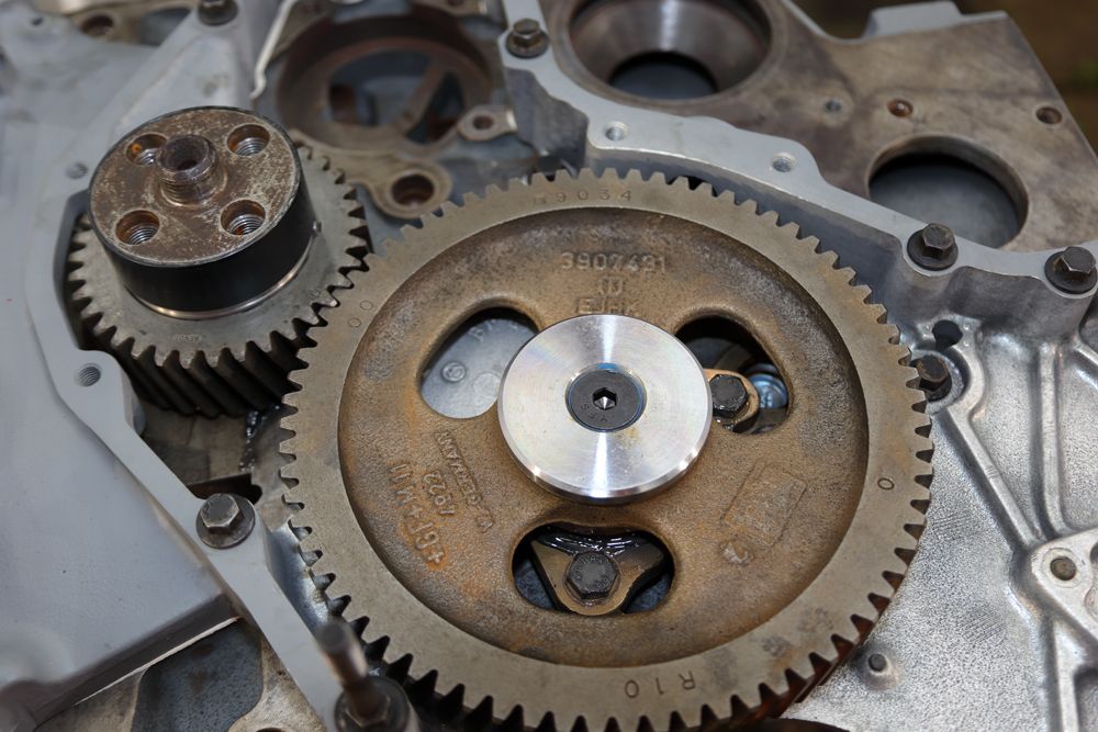
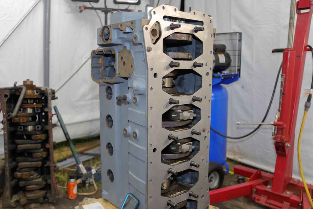
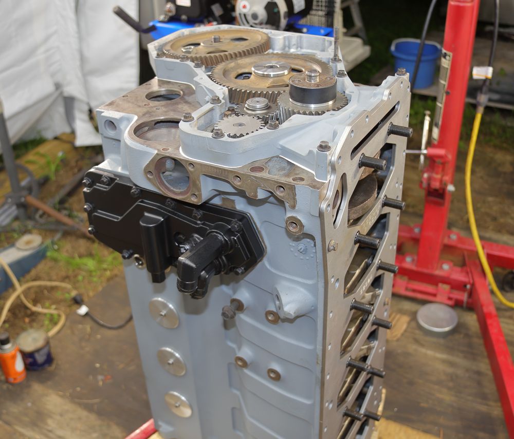
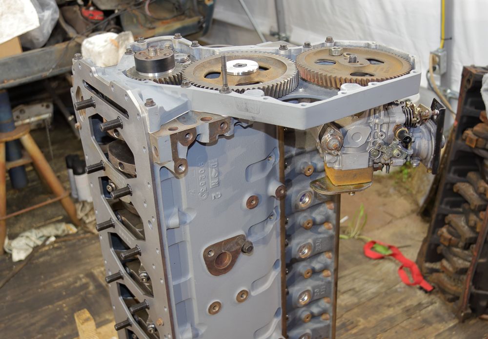
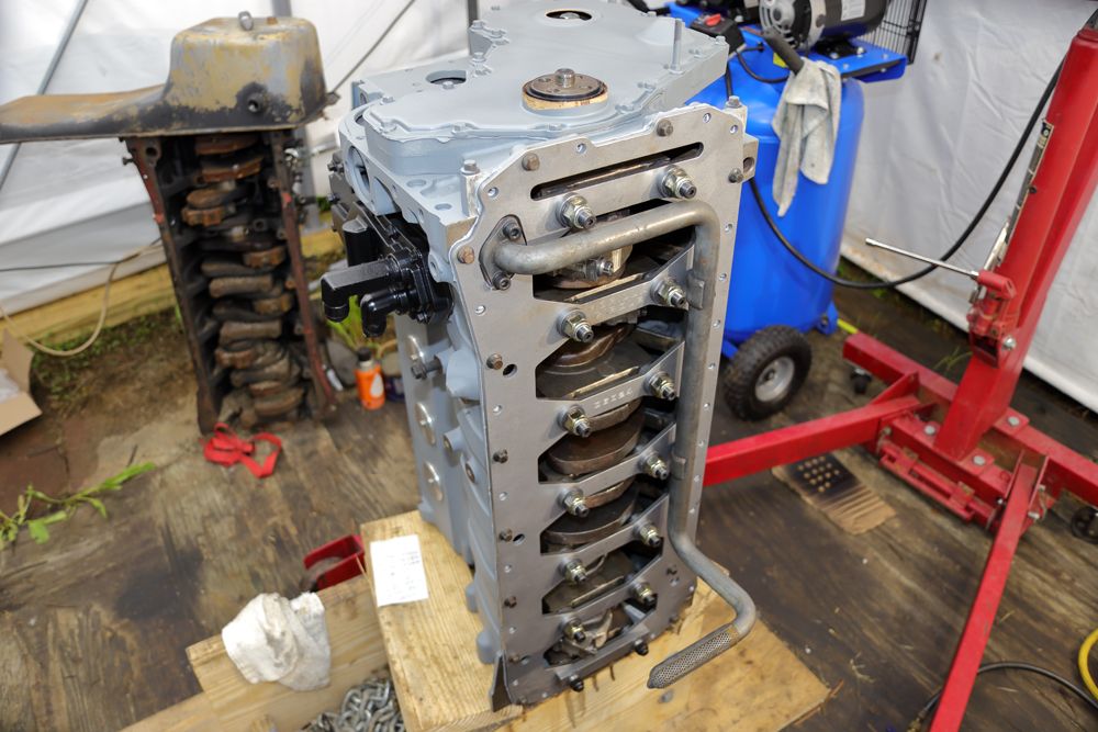
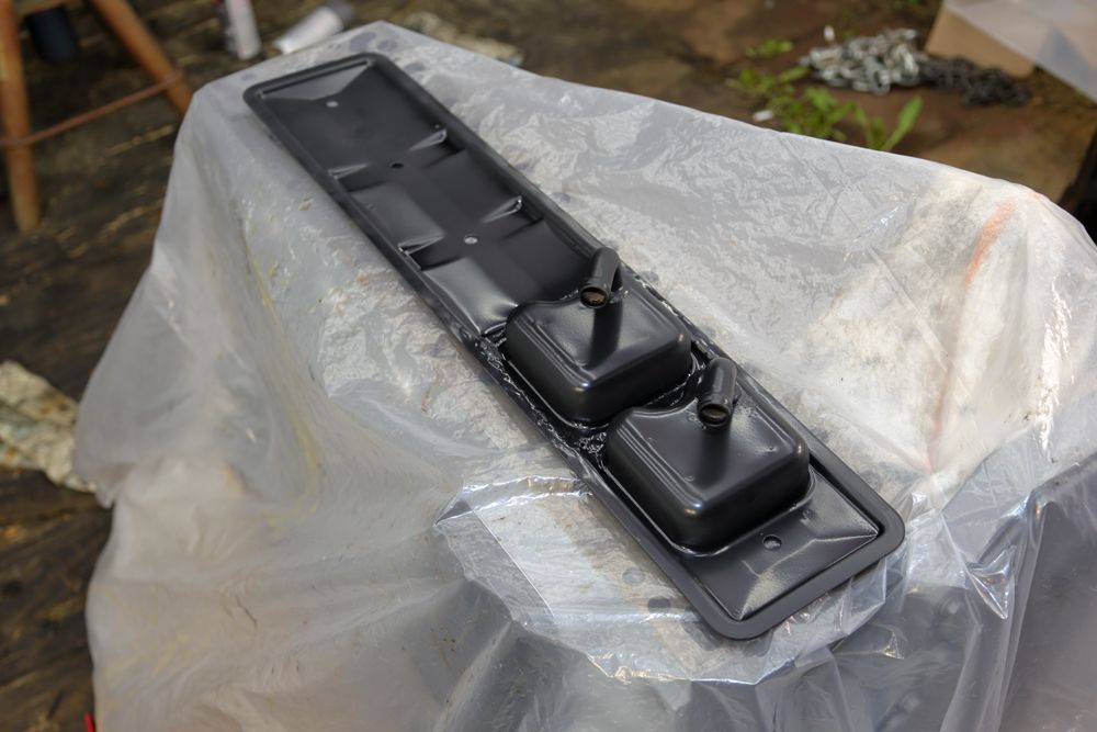
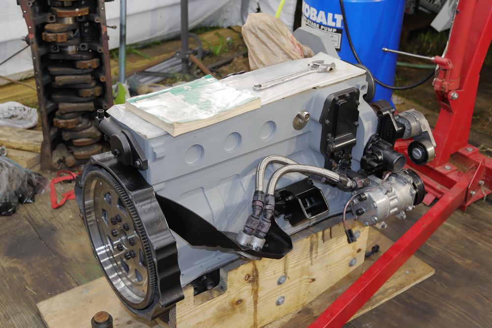
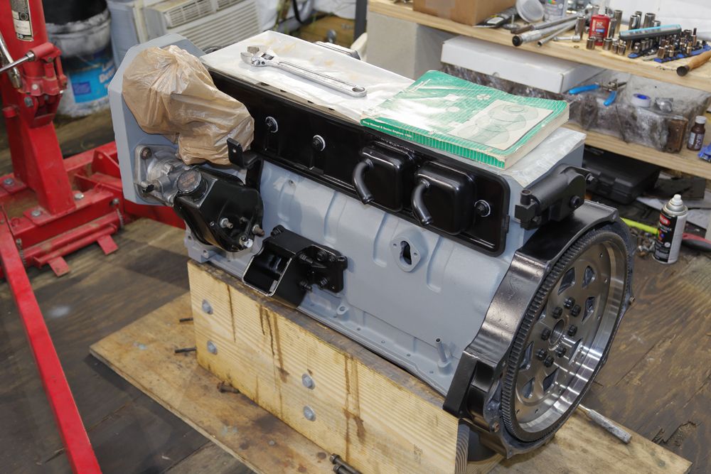
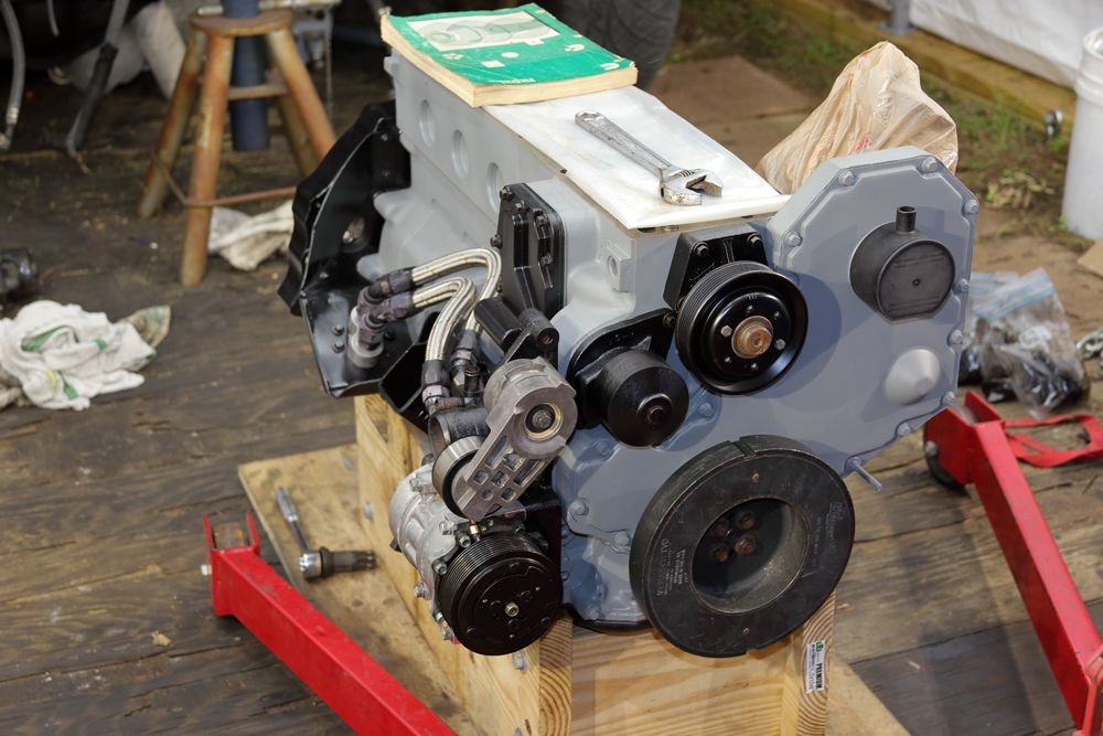
Lots of the build pics here: http://www.devilscastle.net/
Lots of the build pics here: http://www.devilscastle.net/
Last edited:
")
.jpg?width=1920&height=1080&fit=bounds)