
You are using an out of date browser. It may not display this or other websites correctly.
You should upgrade or use an alternative browser.
You should upgrade or use an alternative browser.
Dicking Around . .
- Thread starter BC847
- Start date
BC847
New member
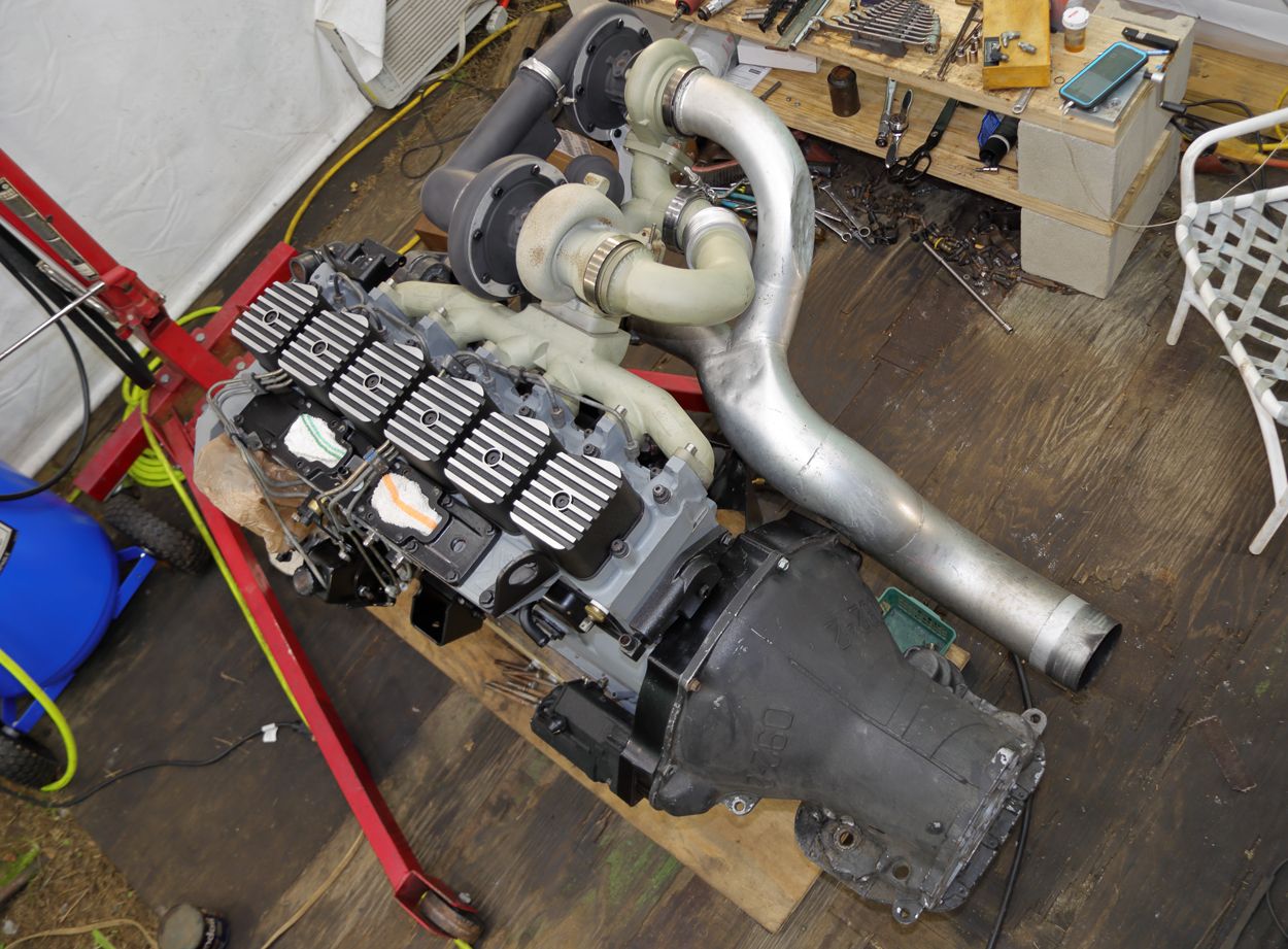
Got a little more done tonight:
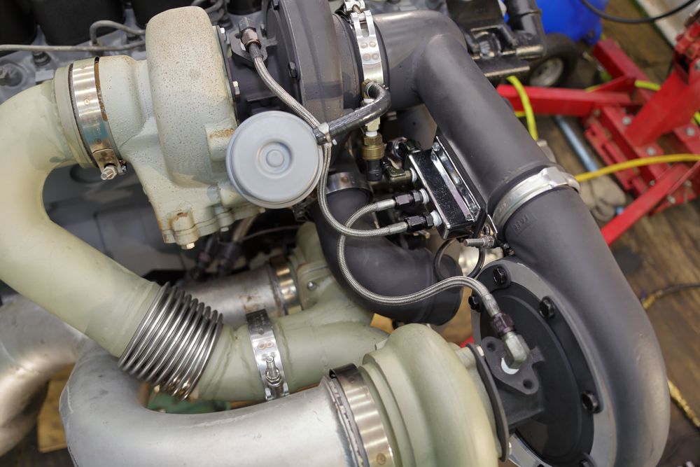
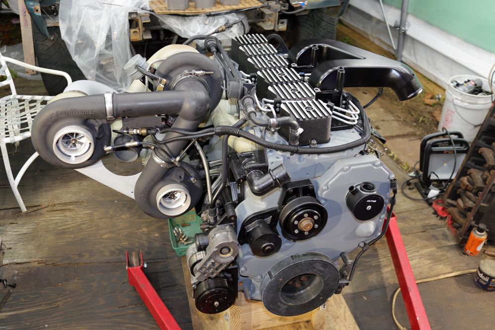
- The Primary pressure sensor assembly installed. The IP's AFC reference signal is from the Tee-fitting to the right.
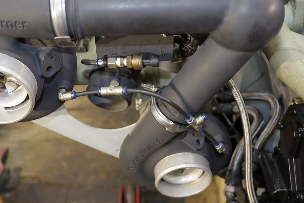
- The Secondary pressure sensor installed.
- The turbo lube-oil manifold. It's -8AN fed and in turn feeds the turbos via -4AN lines.
- The waste-gate actuator assembly.
- The Primary pressure sensor assembly installed. The IP's AFC reference signal is from the Tee-fitting to the right.
- The Secondary pressure sensor installed.
- The turbo lube-oil manifold. It's -8AN fed and in turn feeds the turbos via -4AN lines.
- The waste-gate actuator assembly.
BC847
New member
It was a while back indeed. It's a very different truck today.Man, I still remember your truck in the mag.....seems like a lifetime ago!
Edit: What was your best time? I forget. And at what weight? I'm collecting data now that I'm drag racin my VE again....
Around ten years ago, it was good for a 12.67 @ 6400lbs with an old-school HT3B & S362/65.

Red Sleeper
Active member
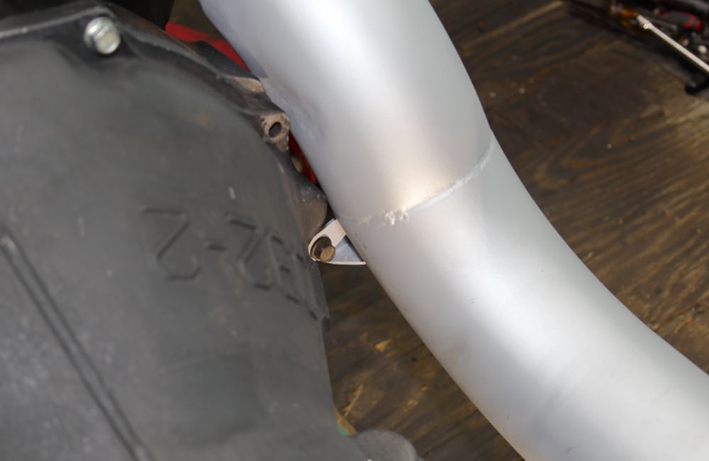
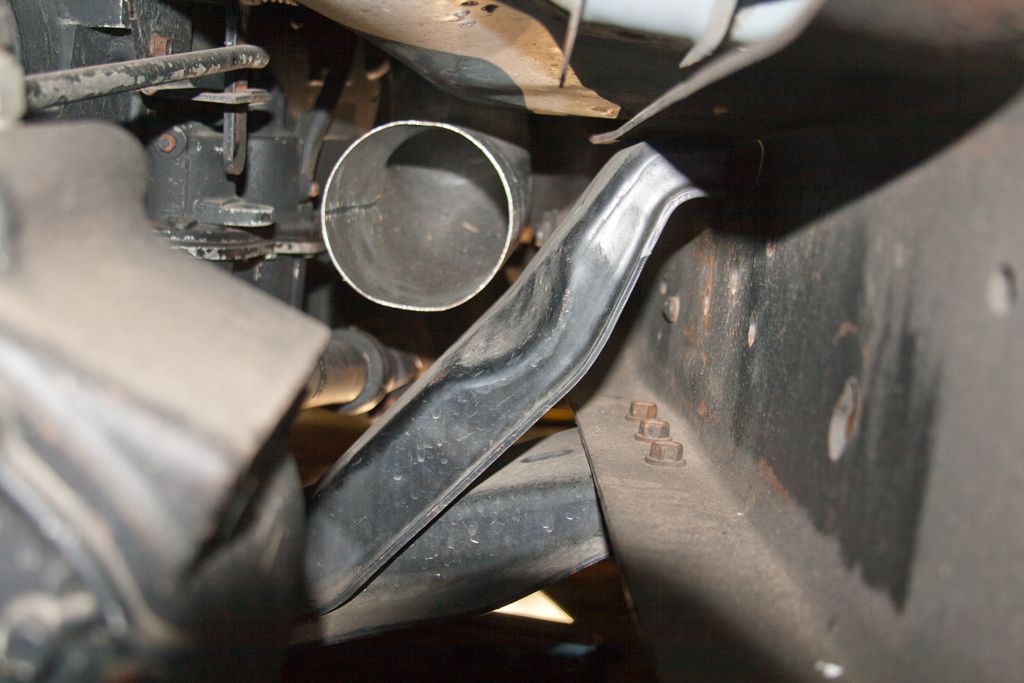
That’s a tight area with a passenger side drop front axle and 4” pipe. How did you squeeze between the frame rail and transfer case?
I’ve seen a flex pipe used to squeeze by the t-case.
I’ve seen a flex pipe used to squeeze by the t-case.
BC847
New member
That’s a tight area with a passenger side drop front axle and 4” pipe. How did you squeeze between the frame rail and transfer case?
I’ve seen a flex pipe used to squeeze by the t-case.
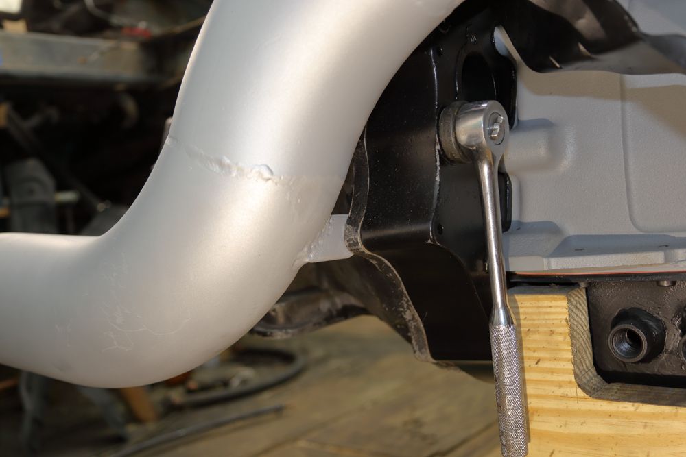
It's 5" (two 3" into one 5").
Starting just aft the bell-housing . . .
I've a 4" section of SS Triple-lock 5" flex to address movement of the engine. That flex spans the frame diagonal . .
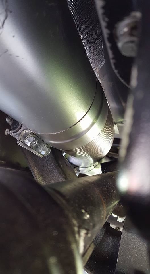
Once past the diagonal, the flex connects to the front of the intermediate-pipe. That pipe is nested in the passenger's frame-rail. As such, while it's tight, a 5" passes with no dents etc . . . . .
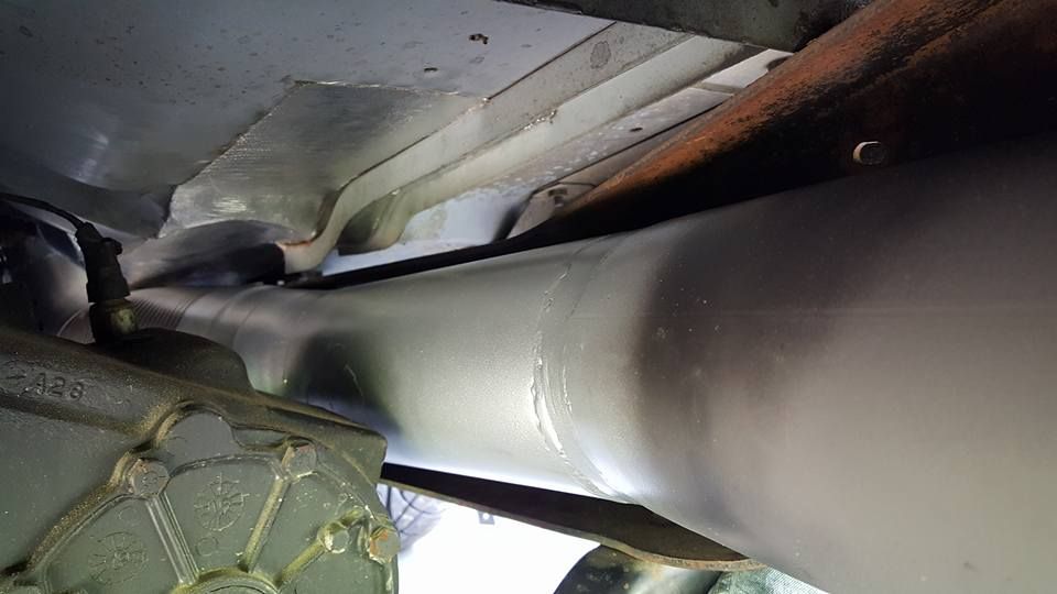
From there, the intermediate-pipe includes a 5" take-off for the temporary bed-stack on its way to the muffler . . .
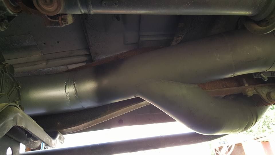
It took a while to whittle-out but, it all fits with no rattling/buzzing.
")
Last edited:
Red Sleeper
Active member
Nice clean exhaust plumbing work. My hang up was over the axle being a 2wd chassis. With the truck loaded 2,000 - 4,000 lbs on the bed, I have contact at the shock. I did use a MBRP kit though.
Is the engine between the frame rails yet?
Is the engine between the frame rails yet?
BC847
New member
:hehe:Is the engine between the frame rails yet?
No.
Still pecking at it though . . .
- Cab heat plumbing.
- Intake feed-horn cleaned up and fitted.
- High-pressure injector feed-lines.
- DATA-logging sensors and the associated wiring harness.
* (Most is just sitting there and easily set aside so as to install the engine with less crap in the way).
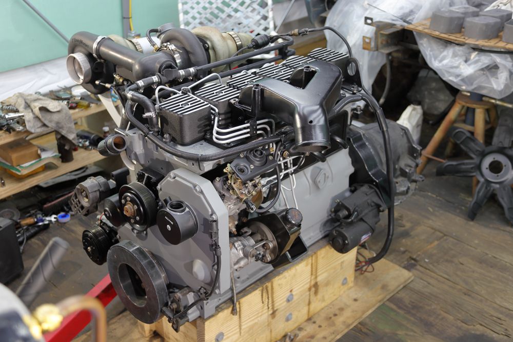
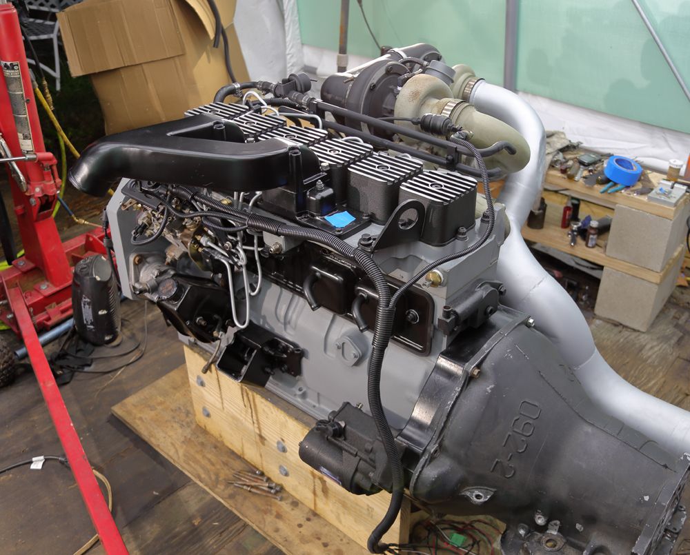
- Still have a few small engine details. Dip-stick tube (mine broke the plastic tube), injection-pump timing-pin doohickey, etc.
- I've been dragging my feet getting to correcting/fabbing/crap regarding the turbo oil-drains and the current remote oil-filter location. I'll have to make it all so as to have it all fit to my liking.
- Clean the skank-ass engine-bay.
- Replace the crack-prone steering-box mounting bracket because, well, it's right there easily accessed.
At the end of the day, I really need to have the heap on the road and be reliable, in the next three to four weeks. Got other life chit to do. You know, . . . like drive the damned thing!
BC847
New member
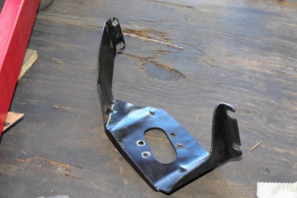
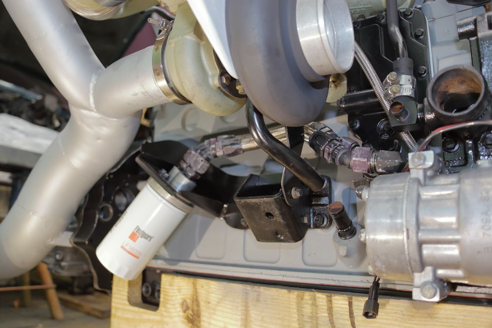
So, back when I first installed the triples, I had to relocate the engine lube-oil filter. I made a bracket for the filter-head that was OK but, when I installed it, I found that I had forgotten about that turbo lube-oil drain port on the engine oil pan. DOH! I had to grossly tweak the bracket to have the oil filter clear the one turbo oil drain port in the pan.
With this new build, I have the opportunity and plenty of room to fabricate/fit a new bracket that clears the two oil drain ports in the pan.
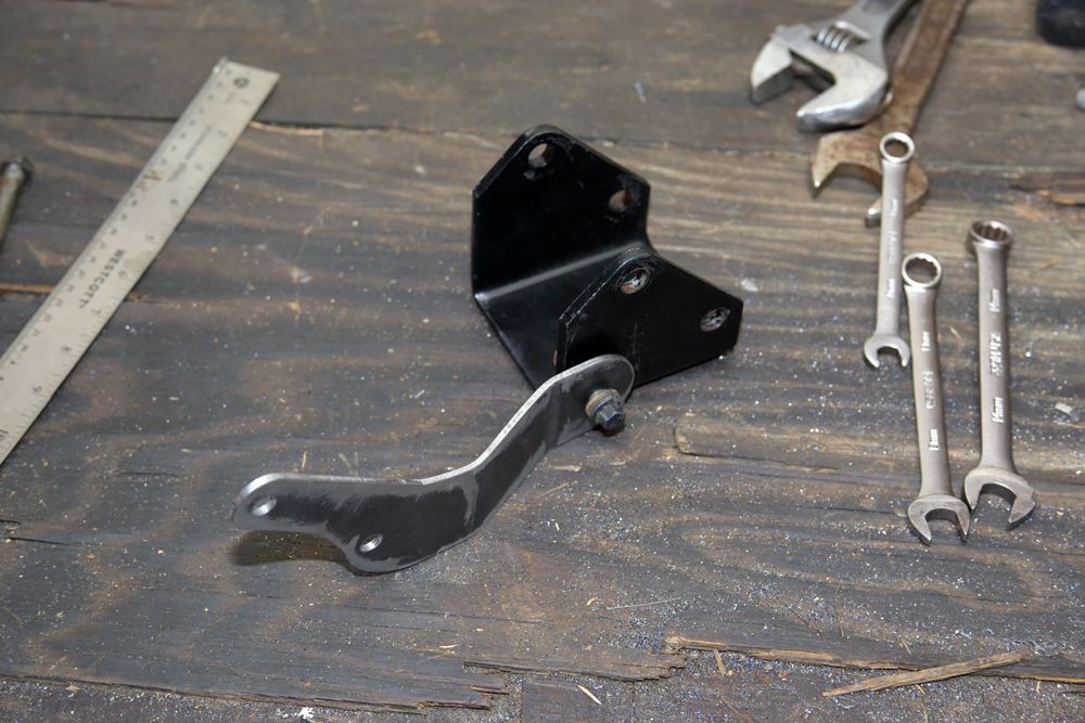
The former ugly Bracket:
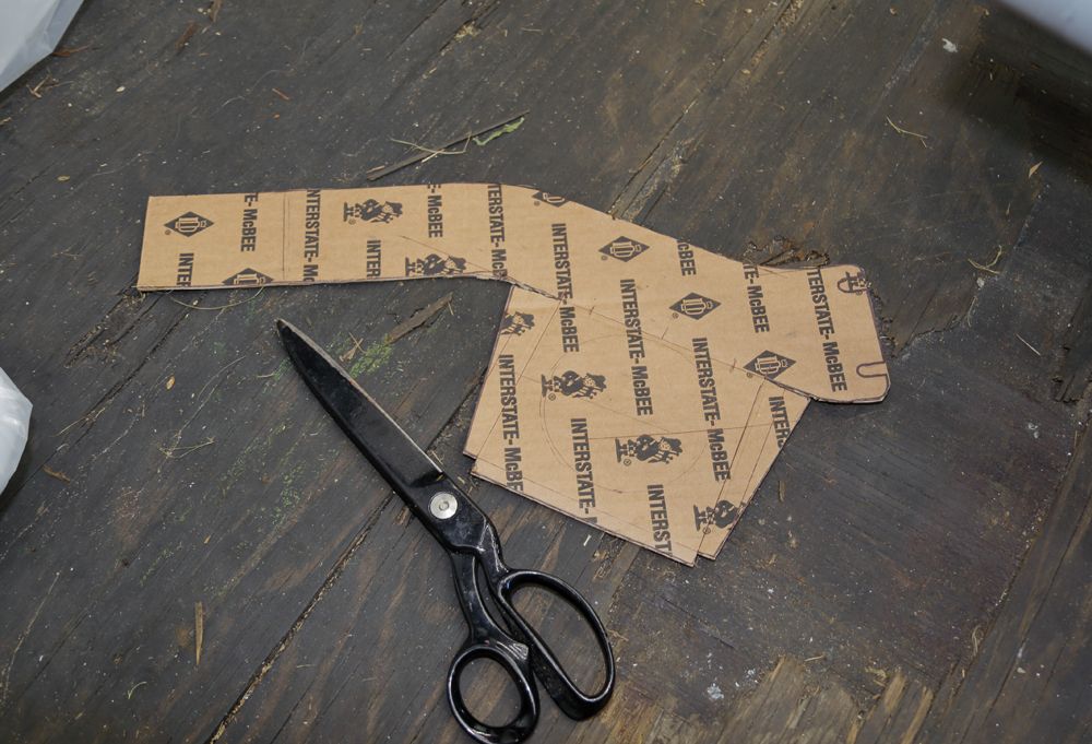
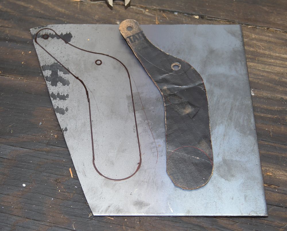
Do some ciphering and make a template:
Transfer that to some 1/8" thick plate-steel, cut it out and fold it up:
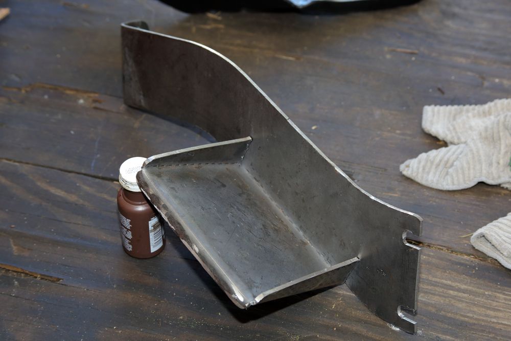
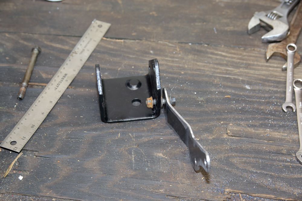
Cut/drill the opening for the filter-head and associated mounting bolts:
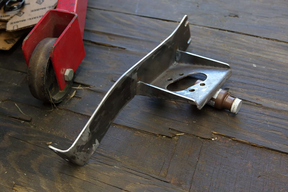
Paint and assemble:
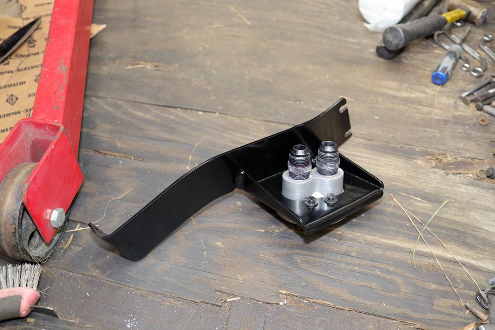
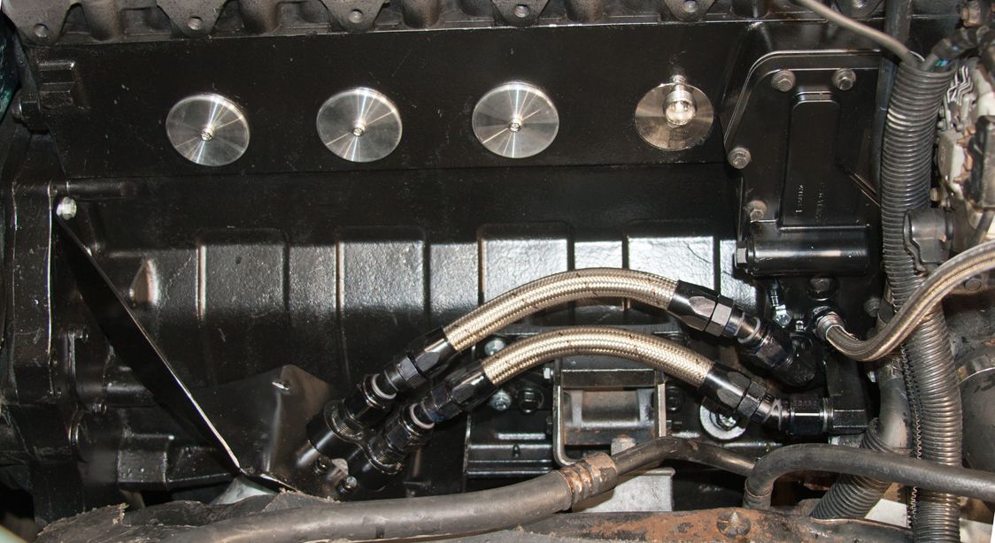
Install and shorten/fit the hoses (plenty of room for the turbo oil drain mess):
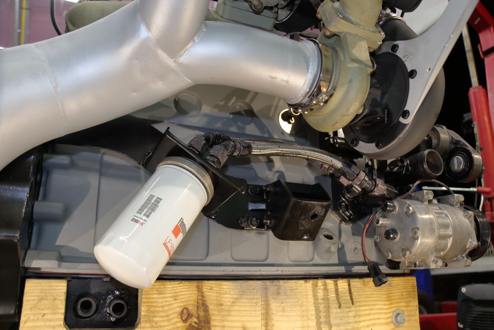
The hoses are well away from the hot stuff.
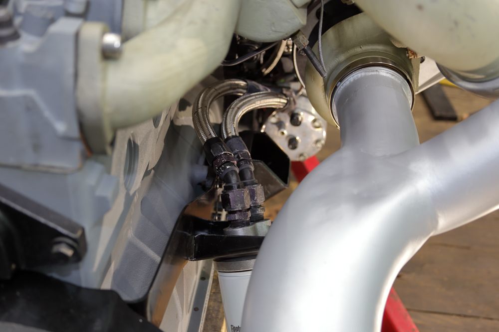
I think it turned out pretty well considering it was made with a jigsaw, anvil, maul and drill.
With this new build, I have the opportunity and plenty of room to fabricate/fit a new bracket that clears the two oil drain ports in the pan.
The former ugly Bracket:
Do some ciphering and make a template:
Transfer that to some 1/8" thick plate-steel, cut it out and fold it up:
Cut/drill the opening for the filter-head and associated mounting bolts:
Paint and assemble:
Install and shorten/fit the hoses (plenty of room for the turbo oil drain mess):
The hoses are well away from the hot stuff.
I think it turned out pretty well considering it was made with a jigsaw, anvil, maul and drill.
displacedtexan
$500 PREMIUM MEMBER
I think it turned out pretty well considering it was made with a jigsaw, anvil, maul and drill.
I'd agree.
Amazing what you can do without the "right" tools, if you're determined and think.
BC847
New member
CAD helps me a lot (Cardboard Aided Design).I'd agree.
Amazing what you can do without the "right" tools, if you're determined and think.
Smokinrebel
New member
You owe me a new monitor. I just spit coffee all over mine.
Im sitting here reading this taking a break from an underground drawing in CAD as we speak.
Thats good chit. Im going to have to steal that one.
Im sitting here reading this taking a break from an underground drawing in CAD as we speak.
Thats good chit. Im going to have to steal that one.
BC847
New member
I dunno about all that. It's just a grocery-getter.This is a high speed racindually.

BC847
New member
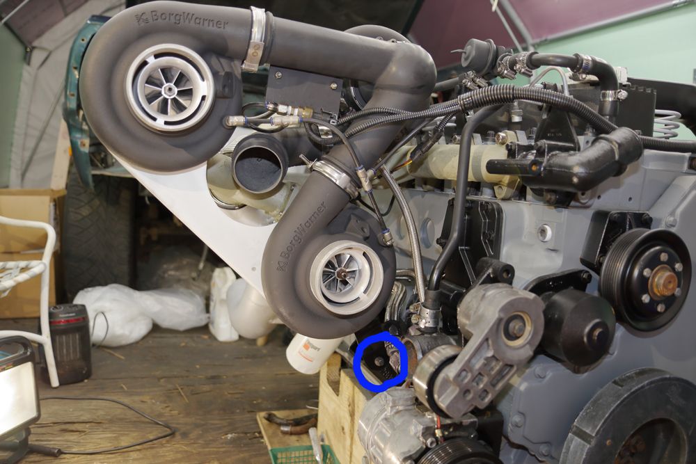
Back when I first built the triple-heap, the lower turbo-group support proved to be less than adequate. It broke. :doh:
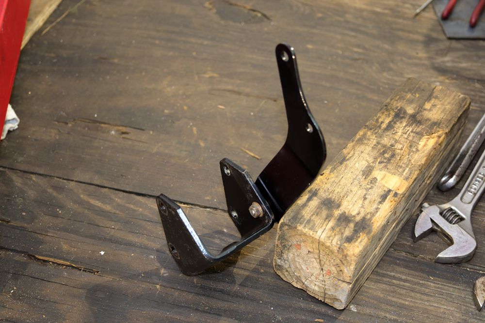
So, I made a new, mo'betta one.
More CAD work:
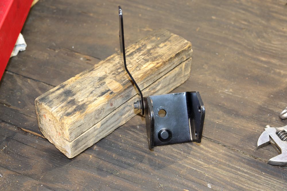
It fastens to the passenger's upper engine mount bracket:
I drilled and threaded a hole in the engine mount bracket and, using a shoulder-bolt, a couple of small/heavy washers and a jamb-nut, made a pivot-point for the support:
A little more tweaking, cleaning and paint reveals this:
It appears to fit as though it was made to go there and allows room for a turbo lube-oil drain to pass under it:
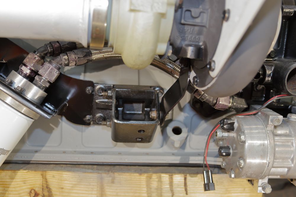
It easily clears all the stuff behind it:
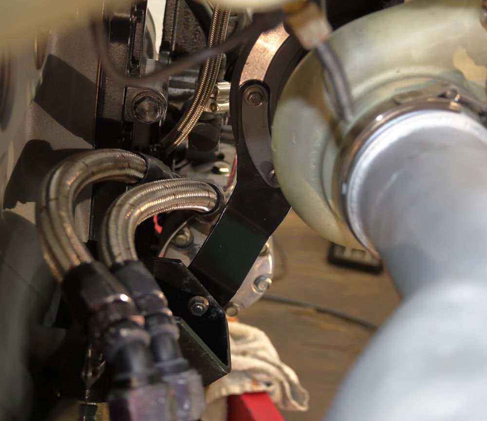
This version better accommodates thermal expansion/contraction of the heap by allowing the mass to pivot to and from the head without excessive binding:
We'll see, huh?
So, I made a new, mo'betta one.
More CAD work:
It fastens to the passenger's upper engine mount bracket:
I drilled and threaded a hole in the engine mount bracket and, using a shoulder-bolt, a couple of small/heavy washers and a jamb-nut, made a pivot-point for the support:
A little more tweaking, cleaning and paint reveals this:
It appears to fit as though it was made to go there and allows room for a turbo lube-oil drain to pass under it:
It easily clears all the stuff behind it:
This version better accommodates thermal expansion/contraction of the heap by allowing the mass to pivot to and from the head without excessive binding:
We'll see, huh?
BC847
New member
Happy Thanksgiving folks! Hope you got some time off to spend with family & friends. If you had to work, thanks for holding the fort down.
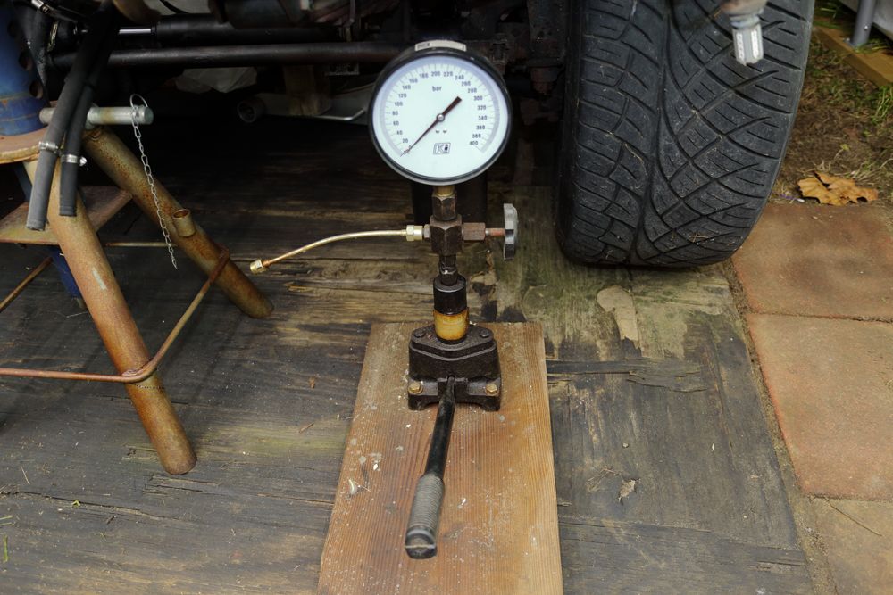
While waiting on parts, I went ahead and disassembled and, by way of the ultrasonic cleaner, cleaned the injector components. I'll reassemble and confirm/adjust the pop-pressure directly.
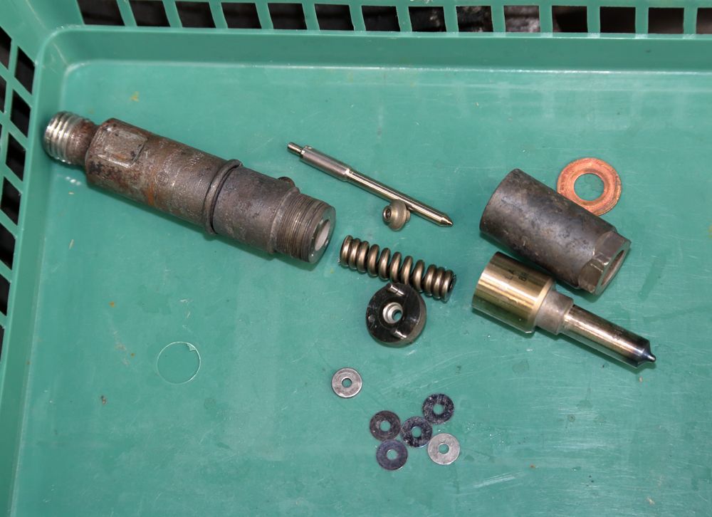
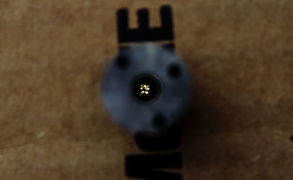
Clean up in there!
This old fella's been of good service all things considered.
I reckon I'll get to them soon enough . . .
While waiting on parts, I went ahead and disassembled and, by way of the ultrasonic cleaner, cleaned the injector components. I'll reassemble and confirm/adjust the pop-pressure directly.
Clean up in there!
This old fella's been of good service all things considered.
I reckon I'll get to them soon enough . . .
BC847
New member
The donor engine included its stock/OEM turbo lube-oil drain pipe. I got to looking at it and couldn't help but see the big difference in the working internal diameter of the flange/fitting. The typical "Billet" Aluminum fitting on the left, stock/OEM on the right.
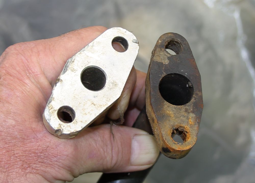
At least one of my primaries was having an issue with lube-oil getting into the compressor. In addition to those narrow drain flanges, I'd committed the sin of tying two turbo drains together. Yeah, I know.
I "Tweaked" that OEM drain-tube to fit the bottom primary.

I may have to pull it up closer to the turbo, as it comes out of the turbo. It's got to clear the passenger's frame-rail.
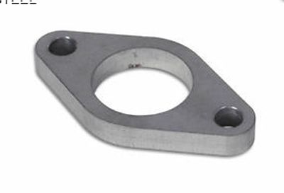
I've got a couple more 1/2" steel T3 lube-oil drain flanges. That and some 3/4" EMT should take care of the remaining turbos.
We'll see, huh?
At least one of my primaries was having an issue with lube-oil getting into the compressor. In addition to those narrow drain flanges, I'd committed the sin of tying two turbo drains together. Yeah, I know.
I "Tweaked" that OEM drain-tube to fit the bottom primary.
I may have to pull it up closer to the turbo, as it comes out of the turbo. It's got to clear the passenger's frame-rail.
I've got a couple more 1/2" steel T3 lube-oil drain flanges. That and some 3/4" EMT should take care of the remaining turbos.
We'll see, huh?
