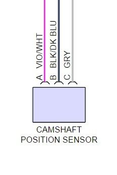
Does anyone have a wiring schematic of the 3 wires that come off the back of the cam senor?
I'm working on installing a 6000 rpm tach in my 2002 and am curious if I can use those 3 wires as a signal for my new tach. Factory gauges work fine, so if getting a signal from the PCM is an option, I'm willing to do that as well.
New tach is a SpeedHut 4 inch 6000 rpm tach designed to be compatible with diesels and requires 1 of the following in order to work:
-an alternator with an 'R' or 'W' terminal
-a crank sensor signal
-a magnetic pulse sensor
The tachometer will read any signal greater than 0.6 volts in any wave form pattern generated from a tach signal source.