White Knight
New member
- Joined
- Aug 18, 2007
- Messages
- 1,380
Has anyone tried using a sleeve over the water pump pulley to create an underdrive effect? That seems to me like a much better solution to reducing water flow then messing with the fins.

Has anyone tried using a sleeve over the water pump pulley to create an underdrive effect? That seems to me like a much better solution to reducing water flow then messing with the fins.
If you look at the pump and the ones with the cone on them, they can really build pressure, giving the extra clearance allows the pump to not build as much pressure.
I'm saying if you slow the pump down by using a larger pulley you would effectively reduce the flow. Less flow wold result in less pressure in this case.
Yes, but with pumps they can have a pump curve and usually they are not linear. So you could ramp the pressure up really fast, say 90% pressure at 50% rpm. So you would ahve to double the size of the pulley to make it slow down. I am just guessing on this.
I don't know what pump curve you are talking about. If I had to guess I think what you mean is: because of the type of water pump used the flow vs pressure is not linear and flow will drop off as pressure increases. I'm not sure how that is really relevant though so I'm lost on that one.
What zstroken is saying is he thinks the relationship between the pump RPM and pressure is not linear. Basically if you were driving it at 2000 RPM with an output pressure of 20 psi, you wouldn't be at 40 psi at 4000 RPM. Changing the size of the pulley may not be effective in that it may take a good size pulley - double or triple the size of the existing water pump pulley to get the effective pressure drop that you would be trying to achieve.
Hopefully that made it a little clearer.
Added pressure in the cylinder head (most likely between cyl. 5 and 6) is what is causing the freeze plugs to blow. If it were pressure in the hole system it should cause the radiator cap to pop and the resivoir should fill. This does not appear to happen.
Good ideas. Something similar may be what has to be done.
Although, I don't believe the radiator cap is in the picture because the pressure buildup is behind the thermostat. If you could get that excess volume around the t-stat you may or may not find that the cap is capable of flowing enough volume to regulate the pressure. I think that if you can move fluid around the thermostat quick enough to keep the pressures in check you would have a chance at keeping the plugs in place.
On a side note: I hate that 15min for editing rule. My first post did not come out as I intended it.
Exactly.
Here is the part that has me a little baffled. How come when you lift the head the first indication is that the resivoir is full (at last from what I have seen) because the radiator cap has released the pressure from the combustion gas? That gas also has to pass through the thermostat.
I believe is that the cylinder head is the culprit, not the thermostat. I believe that the water cannot flow from the area around cylinders #5 and #6, for water ever reason, maybe casting design. I believe that cylinders #1, #2, #3 and #4 have no problem. Would that be why most of the freeze plugs that pop are near the back of the engine? Also why cylinder #5 and #6 seem to run a little hotter than the rest.
I was thinking about this as I was fishing tonight and came up with another question. If you clip the water pump and slow down the velocity of the water moving through the engine, this will give the water more time to absorb heat from the combustion chamber. Raising water temps. Won't this cause the water to boil even worse? Not only that but you would also be lowering the pressure.
I mean the more I think about it this really is a catch 22.:bang
Very interesting idea, I like how you are thinking. It is very possible that this could be the case. Almost makes me wish I had a 24v so it would be easy to put pressure and temperature gauges in the front and back of the head and see what differences there are if any.
The fluid velocity issue is easily solved with the extreme rpms that a p-pump will turn, but for the electronically governed engines it could be an issue. Not something I would want to do on a daily driver.
I think your point about additional pressure and boiling is good, I've never thought about it like that. Definitely takes a lot of wiggle room out for any solution. :kick:
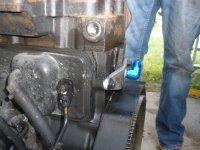
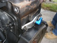
see the plug i'm talking about