New piping for 12 valve

Greenspeed

New member
Joined
Nov 15, 2011
Messages
98
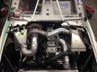
Howdy all. With a little time on the hands since Bonneville got cancelled, figured I could post some shots of what we've been working on. This year, the plan was to take two engine (12V and CR). 12V for veg only and CR for petro and bio-diesel only.

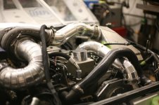
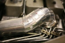
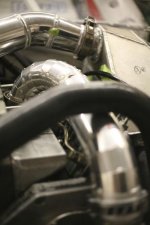
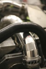
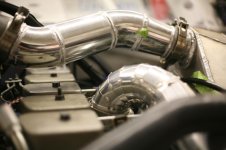
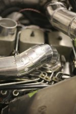
The "passenger side" of the turbo system remains the same between the engines, but due to head and pump differences, the stage 2 intercooler has to change. This led to some serious piping fun on the driver side.

The cooler was finished by the time we started working on tubes, but the we got these all tacked together and ready for welding in one day (three of us working on it), then welded it up the next. Didn't have a chance to take many pics of it welded up yet, but will get some of those if y'all are interested.

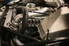
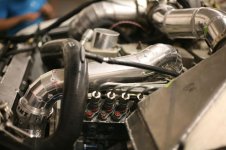
There are a few tight spots with this setup, and we lucked out with having an extra clamp to make the section around the adjustable pump gear removable. Otherwise adjust the timing would be a HUGE pain. Still working out some kinks in the engine, should have it dynoing soon though.

Enjoy and let me know what you think!
 

Attachments

  • IMG_7859.jpg
    IMG_7859.jpg
    55.5 KB · Views: 0
  • IMG_7861.jpg
    IMG_7861.jpg
    32.1 KB · Views: 0
  • IMG_7865.jpg
    IMG_7865.jpg
    39 KB · Views: 0
  • IMG_7867.jpg
    IMG_7867.jpg
    52.7 KB · Views: 0
  • IMG_7868.jpg
    IMG_7868.jpg
    52.6 KB · Views: 0
  • IMG_7869.jpg
    IMG_7869.jpg
    44 KB · Views: 0
  • IMG_7874.jpg
    IMG_7874.jpg
    25.7 KB · Views: 0
  • IMG_7873_2.jpg
    IMG_7873_2.jpg
    23.7 KB · Views: 0
  • IMG_7872.jpg
    IMG_7872.jpg
    46.1 KB · Views: 0
  • IMG_7871.jpg
    IMG_7871.jpg
    28.2 KB · Views: 0
  • IMG_7870.jpg
    IMG_7870.jpg
    41.5 KB · Views: 0
  • IMG_7876.jpg
    IMG_7876.jpg
    31.1 KB · Views: 0
Looks pretty nice, definitely an absolute TON of welding going on there.

Can you take a few pictures farther back showing the whole setup? Hard to get a handle on what's going on here.
 
F' that crap lol. Nice work, but damn thats alot of welding and cutting and fitting.
 
Looks pretty nice, definitely an absolute TON of welding going on there.

Can you take a few pictures farther back showing the whole setup? Hard to get a handle on what's going on here.

I can definitely do that, it's out of the truck right now though. I think I've got one on my phone though.
 
overview shot. As you can see from the other side of the engine, we kinda like the pie cuts. Good practice for the TIG skills…
 

Attachments

  • outside.jpg
    outside.jpg
    86.3 KB · Views: 0
That's very sharp looking. Very nice work. I couldn't imagine welding all that in one night. That's a Tylenol induced bed time after that.
 
That's very sharp looking. Very nice work. I couldn't imagine welding all that in one night. That's a Tylenol induced bed time after that.

Ya, we end up with some pretty long hours around Speed Week time. Thanks though! We've learned A LOT over the course of this project.

And newsmoke, yes, two stages of intercooling. Much time was spent with Garrett engineers, and two ICs the same size (i.e., same size cores) were determined to provide the best cooling. We have lots of data that I'm more than happy to share. If interested, just let me know what you'd be interested in.

Thanks! I built a similar set over the winter and used two 4.5"x4.5"x12" precision cores. I would be very interested to know all of the data that you are willing to share about the setup.

Did you perform testing with and without interstage cooling?
Did Garrett provide information on secondary compressor efficiency with and without cooling?
What did Garrett recommend for pumps? Or did you just run boat pumps?

On the setup I made we noticed great spool and compounding, I'm assuming due to the fact that the secondary is taking in much cooler air and the fact that we reduced piping and cooler area by 60% or so.
The only problem has been pumps and plumbing for the heat exchangers
 
Hi Jared,

We did not do any testing/running without the intercoolers, everything was with both installed. We now have access to a more long term dyno situation at Adrenaline Truck Performance, so we hope to have the chance to do more in depth testing. The kind where engineering predictions can be made after collecting all the data.

I can't really comment on what Garrett did. Anything they did provide is considered confidential, sorry :(

They didn't recommend anything other than a flow rate. We used a bilge pump, I'll take a picture and post it up. It works quite well. One of the guys wrote a report on JUST the water part of the IC system, I'll see if I can dig that up. Basically, a 1.25" hose runs from the pump to a manifold up front that has 4 1" lines coming off it (one to each core, 2 cores each IC). The return is opposite. Just this year we switched to all JIC lines. We were using heater hose and plumbing fittings, which also worked, but looked bad and were a mess to deal with.

I have a sample excel sheet with most of the data we collect, I'll see if I can upload one of those. Would that help you out at all?

Dave
 
Mostly I'm just curious to see any and all information that I can, as compound turbo and intercooled setups are so rare in an aftermarket/performance environment. I completely understand the confidentiality as tons of money can be invested in these setups.

Thanks for all the information and pictures that you do provide us with

Here is a Dropbox link for data from one of the runs at Bonneville last year. I tried attaching, but the forum won't let me directly attach an .xlsx file. If the link is broken in the future, just let me know and I'll re-up. If the header is (F), it's in degrees fahrenheit, if it's (P ), it's psi. IC1hot (F) for instance is temp going INTO stage 1 intercooler. IC1cold (F) is coming OUT OF stage 1 intercooler.

I'm not convinced that the Intercooler Water temp is correct, btw. We didn't add anything to the water to allow it to get below 32F without freezing.

We are adding post turbos temp this year as well. That was something Garrett requested in order to get closer to a complete analysis.

The front/rear left/right on the far right is for ride height. I don't think this spreadsheet has the smoothed data in it though. That stuff is pretty noisy.

I'd add a pic of the water pump, but the water tank is buried beneath a bunch of stuff right now. I will get that soon for you.

If you have any other questions, please just let me know. Anything we can do to advance this stuff is what we are all about.
 
also, here is an example of the Stage 1 intercooler.

We have since moved from pipe fittings with rubber hose slipped over and hose clamped to braided JIC lines (thanks to Western States CAT). Those are MUCH nicer to deal with...
 

Attachments

  • an_den.jpg
    an_den.jpg
    48.7 KB · Views: 0
Last edited:
Thank you for taking the time to post that information! I have yet to get to a real computer but my tablet cannot open that drop box
 
Oh, ok. It's an Excel file. Is there some kind of format that would work best for you?
 
That set up looks amazing to me. Love the pie cuts. I read your description and it sounds like you have two air to water coolers. One per stage. However I don't see both coolers in the one picture of the whole truck. Are you cooling the air between stages or just before it enters the engine? If I read correctly you are interstage cooling, I must not be seeing the other cooler.

Thanks,
Jay

Thanks! It's been a lot of fun working on this project.

I'll post up another shot when I get to computer. In the "overview" shot up there, you can barely see the intercooler behind the cold pipe (they are connected).
 
A better shot of the 12 valve engine bay:
 

Attachments

  • photo1.jpg
    photo1.jpg
    76.6 KB · Views: 0
That's a fantastic build! In the data, is IC1 on the passenger side and IC2 on the drivers side? Are turbo size specifications public knowledge?
 
Back
Top