Yet another VGT controller thread

Thekid760

New member
Joined
Jun 12, 2008
Messages
475
I found a few older VGT control threads, but they were all closed so I couldn't bump them up. So I figured I'd start a new thread for input on my VGT controller idea.

It isn't a new idea, but a modification on the old boost/dp double acting air cylinder one, modified to try and add and exhaust brake.

Bear with me, it's a little difficult to explain so I also made a diagram.

VGTController_zps23d77659.jpg


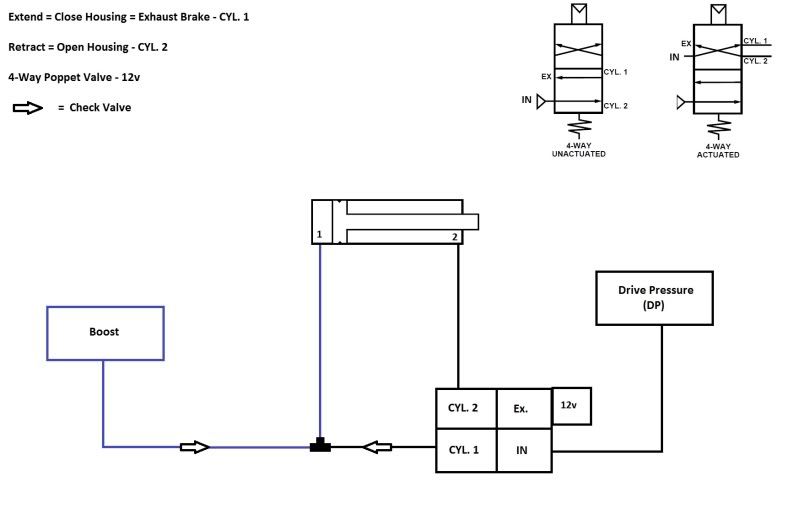
I like the idea of drive pressure and boost pressure equalizing itself, this seems to me as the most efficient way. But unless you run compressed air I haven't seen any like that with an exhaust brake functional.

As you can see, I have it set up so extending the cylinder will close the housing down and retracting it will open. I will use dp to open the housing and boost to close, hopefully keeping the operation smooth.

I am essentially planning on hooking up a controller that when activated will leave the retract (opening) side open to exhaust, and will switch the dp to the extend side. I figure most EB setups seem to have 40-60psi of dp so I'm hoping that will be enough to keep it closed. I plan on using a larger diameter air cylinder so I can get as much force as possible with only the 40-60 psi.

I have the cylinder mounted in the extend/boost and dp/retract for two main reasons:
- when the dp is forcing it into EB mode, it will be able to take advantage of the full surface area of the piston vs only part of it because of the rod.
- This will also allow me to easily mount a spring over the rod for automatic closing of the housing, and/or return however you want to word it.

The check valves are so I dont put dp into the intake, and I dont create a boost leak when the controller in inactive.

I was talking to BramanteCummins and he brought up that the housing needs to come to rest at a neutral position so as not to load up the engine at idle and off throttle. He mentioned a spring stop that will keep it just out of the EB, but can be overcome by the force of the air cylinder to allow EB.

Thanks for bearing with me, any input will be appreciated.

Clear as mud? :Cheer:
 
Definitely clear as mud.

Can you explain the diagram a bit more?
So boost and drive pressure are obvious, so is the actuator with the two sides, and even the check valves, but what is the small box that says 12v, and what is cyl1/2/in/ex?

And finally, I was thinking of possibly doing something like this but even more simple, but probably not as efficient. I was going to try adjusting the actuator to fixed positions to see where works best for the 'small turbo', and then possibly just weld a stud to make it so the arm doesnt go past there. Then use boost to control a standard wastegate actuator.
 
Last edited:
The 12v is just the electric connections.

"In" is the inlet to the controller from the exhaust manifold (drive pressure source).

"Exh" is the exhaust port of the controller. This allows pressure to escape the cylinder.

"Cyl 1" is the port on the controller that connects to the boost side (port 1) of the air cylinder.

"Cyl 2" is the port of the controller that connects to the drive pressure side (port 2) of the air cylinder.

When the controller is not active (switch off) the air flows from "in" to "Cyl 2" allowing the air cylinder to operate like normal.

When the controller is active (switch on) the air flows from "in" to "Cyl 2" allowing (port 1) to be open to the air and allowing drive pressure to now be in (port 2) causing the air cylinder to extend, over riding the spring and causing the vgt to close all the way.


Misspelling courtesy of my fat fingers...
 
Negative.

The arm is being moved by a double acting air cylinder.

the air cylinder is being moved by drive pressure and boost.

The EB is being activated by a 4-way air controller. The 5 boxes grouped together under the drive pressure box is the controller, I just separated the 4 ports and for some reason I added the electronics of the controller (12v) even
Though it's not really relevant.


Misspelling courtesy of my fat fingers...
 
All the weird box does is switch the ports around basically. This means that drive pressure will close the housing. And as it closes more you get more engine braking
 
It is easer to buy a electric contoller from fleece, well I guess that depends on if you have a electric actuator or air one on the turbo you are using.
 
I think it also depends on what turbo you have. Some boxes aren't able to use the signal fleece uses. There's a pwm and a CAN type signal. Even if you bought the correct box, not all turbos are the same. The gear on mine is offset whereas some others are centered
 
I knew their are the two diffrent types but I don't know who still uses the pwm actuator. Detroit did on the pre production test Epa 07 series 60 but when those engines where brought up to production we switched to can. The cummins use can too. I am guessing since you say vgt & not vnt your talking about holset turbos. And I haven't seen a off set gear. did you do that yourself?
 
Easier, yes, but pricey. And it's still relying on electronics which is a big part of the issue with these turbos. I'd like to keep it a mostly mechanical setup.

I can also take more pride in knowing that its something I designed and made.
 
I understand & respect doing it your self. I built the exhaust maifold my self on my truck. I do like electronics my self. It is alot easyer to hit key that ajust stops. Don't be scard of the electronics. Electronic are so much more flexable. And It is the turbo that fails usually not the actuator. the sector shaft start sticking and the gate binds up. the electronic actuator does a swipe the full range of motion every time the key is turned on.
 
I said swipe I ment to say sweep. We replace a lot fewer electronic turbos than air activated vnt's. And bramantecummins does you turbo have a 66 mm inducer & if so where did it come from?
 
His is a 66/67, mine as well.

I bought the same wheel as in his turbo and had it installed by fleece. His came like that from holset.


Misspelling courtesy of my fat fingers...
 
Why not use spring pressure to close it to a set point and boost pressure to open.then all you need is a separate diaphram to push it past the normally closed position to activate the exhaust brake. You could use boost pressure to fill an air tank and then use a solinoid to control the exhaust brake function with a bleed for release. Then you wouldnt need boost pressure which seems to be problematic.
 
I understand & respect doing it your self. I built the exhaust maifold my self on my truck. I do like electronics my self. It is alot easyer to hit key that ajust stops. Don't be scard of the electronics. Electronic are so much more flexable. And It is the turbo that fails usually not the actuator. the sector shaft start sticking and the gate binds up. the electronic actuator does a swipe the full range of motion every time the key is turned on.

Spill the beans. I'm mechanically controlling it just so I can figure the damn thing out. And fleeces controller is only for a 24v+ motor. I've done extensive research and nobody but fleece has it done via electronics. I'll get a pic of the gear location in the morning though
 
Fleece doesn't have the connectors for the Volvo mounted turbos... they freaked out when I sent a customer's turbo in for their billet 63mm wheel, asked if they needed to make it work too LOL They seemed pretty relieved when I told them I would be building mechanical controls for it.

This is essentially the idea that I had, but mine is a touch more simple. It's based off my normal use of the stock WG actuator and a linear actuator for on the fly adjustment. It just uses DP to the actuator and a pneumatic switch/vent to close off DP signal/vent the actuator when EB is desired.
 
Simple is better as far as mechanical control goes. When you mix electronics with it you then need a programmable controller. There's too many variations in drive pressure and boost to make a controller like the op shows work. If you don't use dp and boost pressure sensors with an electronic control module it will work great some of the time and other times it will be a pita to drive.

If you want simple and effective use a spring for return to a set point for low boost, an air cylinder for EB activation and a WG actuator to open the vanes.
 
The "controller" in my op is nothing more than a readily available 12v air solenoid.

It has two positions, first is normal, not actuated. That allows the air cylinder to work like normal, self regulating dp vs boost like many have done with success. When activated (by a switch I control) it simply just diverts the dp to the boost side.

It seems simple enough to me, but I haven't been playing with these like a lot of you have so it's all just theory to me.


Misspelling courtesy of my fat fingers...
 
Back
Top