Cummin-a-long
Big Angry
- Joined
- Jul 24, 2008
- Messages
- 787
Here's the video slowed down to 5 RPM's...
[ame]http://www.youtube.com/watch?v=tQP6BvfM2Qw[/ame]
[ame]http://www.youtube.com/watch?v=tQP6BvfM2Qw[/ame]

Amazing work so far. It would be exceptional if you continued the analysis like you described.
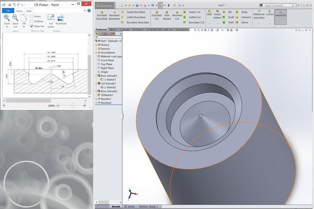
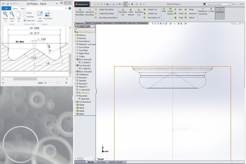
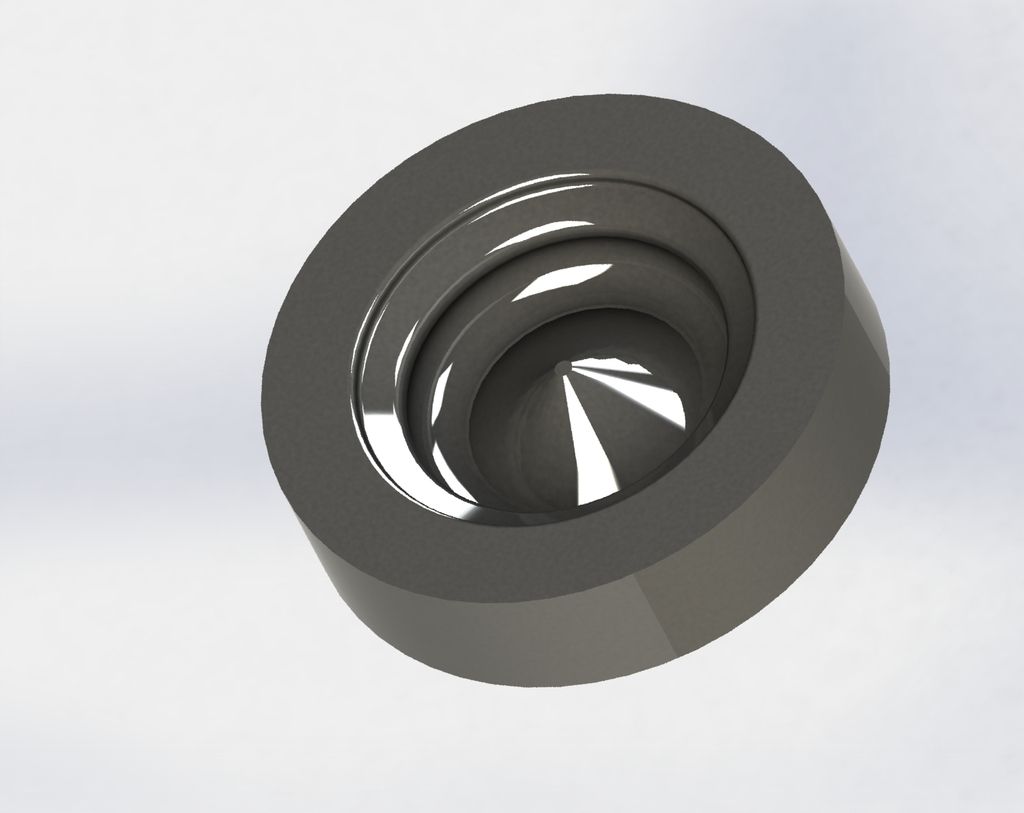
If you want to see it taken out that far, we'd have to redo the piston with the actual measurements and not just the eye-ball setup I did there. The other thing we'd need is someone that has a head and injector out on the table to get an installed protrusion depth.
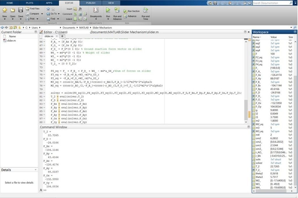
After that it's just setting up the redundant calculations, which excel or matlab can do quickly. These would give you your true min/max points. You still have to calculate your mass flow rate for your air, so you can calculate what you actually need in mass flow rate for your fuel at each given point.
That's a LOT farther than I had planned on taking this setup.
Can we do it? Sure.
Can we set it up so all you have to do is plug in a few variables? Sure.
Do I really want to do that much work? Not really.....
This may be something I'd be interested in sitting down with a FEW others and breaking it down into manageable portions though. Making seperate functions, like I showed in the earlier calculations with matlab or excel, and letting those feed / call each other could make a really powerful calculator for this.
I usually don't give a crap about sharing some of the simpler tools I make but some folks get a little touchy about that.
Awesome work!
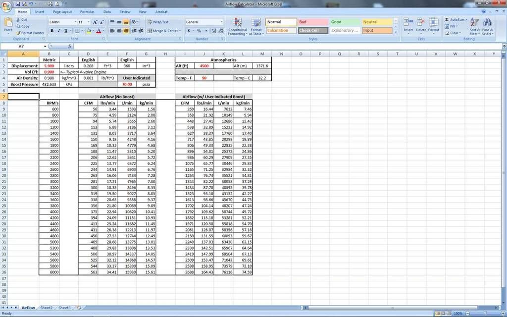
Isn't .900 volumetric efficiency a little overly optimistic for these engines? Or is that assuming it is under forced induction and taking that into account?