slrrls
Water fuel 1st diesel 2nd
- Joined
- Jun 30, 2012
- Messages
- 135
Have been driving the 99.5 with a 12 valve and a 47RH for about 5 years.
This was the thread where it began. If anyone has questions on how to set it up then just read the following thread from front to back first and you'll learn what to do.
http://www.competitiondiesel.com/forums/showthread.php?t=137386
I'm trying to sweeten the shifting now.
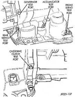
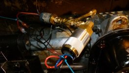
I have the two pressure switches coming off a The rear servo test port. They come off and then T so both pressure switches are working on just the rear servo pressure port.
I see it as a problem that I can't get the two pressure switches isolated on their own switch.
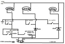
There is a toggle for both switches to work in an automatic mode that works properly.
-Then a toggle to switch the overdrive on which when I switch it both switches activate at their set pressure to come on.
-Then another toggle to turn on just the Lock Up but when I switch it both pressure switches turn on a their set speed.
The only thing I can think that is hindering just one switch working on it's own toggle is that I have the pressure switches on on test port connected to a T.
So when I actuate one somehow the pressure transfers through the T and actuates the other switch as well.
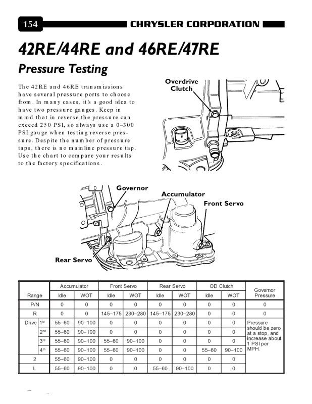
The question puzzling me is if it is ok to connect one pressure switch to the Governor test port and one swich to the rear servo test port or one of the other ports so both are isolated?
And has anyone else seen this problem and what did you do to solve it?
I'm also wondering if I could get the 99.5 trucks transmission pcm to shift the overdrive for me? Then I would only need to put the Lock up on a pressure switch and toggle. If that is possible then what Pin would I need to choose?
I even wonder if I could run the lock up from the 99.5 computer on 54 as in this diagram?
http://www.tstproducts.com/Torque%20Converter%20Lockup%20Switch.pdf
This was the thread where it began. If anyone has questions on how to set it up then just read the following thread from front to back first and you'll learn what to do.
http://www.competitiondiesel.com/forums/showthread.php?t=137386
I'm trying to sweeten the shifting now.
I have the two pressure switches coming off a The rear servo test port. They come off and then T so both pressure switches are working on just the rear servo pressure port.
I see it as a problem that I can't get the two pressure switches isolated on their own switch.
There is a toggle for both switches to work in an automatic mode that works properly.
-Then a toggle to switch the overdrive on which when I switch it both switches activate at their set pressure to come on.
-Then another toggle to turn on just the Lock Up but when I switch it both pressure switches turn on a their set speed.
The only thing I can think that is hindering just one switch working on it's own toggle is that I have the pressure switches on on test port connected to a T.
So when I actuate one somehow the pressure transfers through the T and actuates the other switch as well.
The question puzzling me is if it is ok to connect one pressure switch to the Governor test port and one swich to the rear servo test port or one of the other ports so both are isolated?
And has anyone else seen this problem and what did you do to solve it?
I'm also wondering if I could get the 99.5 trucks transmission pcm to shift the overdrive for me? Then I would only need to put the Lock up on a pressure switch and toggle. If that is possible then what Pin would I need to choose?
I even wonder if I could run the lock up from the 99.5 computer on 54 as in this diagram?
http://www.tstproducts.com/Torque%20Converter%20Lockup%20Switch.pdf
Attachments
Last edited: