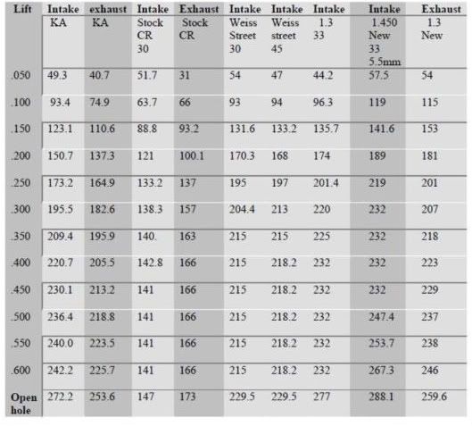
ANYONE w/12v & 24V Ported Head Flow #'s???

Didn't you drop a valve though too? Was it an intake valve or an intake valve acting as an exhaust valve?

I dropped an intake intake valve lol. My cam was 1/2" recessed into the gear which according to those I asked closed my piston to intake valve clearance up. All the exhaust valves looked good when I pulled them.
 
i forgot to mention these numbers were 12v flow numbersin my previous post. i flow tested a 24v p&p head with intake cut off and 1.4oo in. valves that flowed in the mid 260's cfm at .800 lift. this was a 2nd gen 24v head that was another companies p&p job.
 
used intake valves all the way around. But I can tell you this, it dropped my boost from 46psi-47psi to 38psi-39psi, spoolup was faster, smoke was less dense and EGT's rose slower and maxed out lower.

hmmm I am going to use exhaust valves all around, and re cut the seats all to 45*
 
i forgot to mention these numbers were 12v flow numbersin my previous post. i flow tested a 24v p&p head with intake cut off and 1.4oo in. valves that flowed in the mid 260's cfm at .800 lift. this was a 2nd gen 24v head that was another companies p&p job.


.800" seriously dude?? How do you plan to open the vavle on a Cummins to .800? Flow numbers at that kind of lift are completely erroneous!!!
 
hmmm I am going to use exhaust valves all around, and re cut the seats all to 45*

Exhaust valves all around? Why would you go to a smaller valve on the intake? Or do you mean exhaust valves the same size as an intake valve from a different application?
 
.800" seriously dude?? How do you plan to open the vavle on a Cummins to .800? Flow numbers at that kind of lift are completely erroneous!!!


You just take the pistons out silly. Lots more room for valves that way.

Come on Scott, get it together man:hehe:
 
ScreenShot001-4.jpg
 
Here are some values I figured for a 360in^3 engine turning 2800rpm.

360in^3 = 0.208ft^3

So given 6 cylinders, each cylinder displaces 0.0347ft^3 at 100% VE.

Just for simplicity's sake I'll just assume the intake valve is open for 180 degrees of crank rotation. So at 2800rpm you've got 0.00035714 minutes per rev, or 0.0001785 minutes to travel the 180 degrees. Meaning that same time to draw in the 0.0347ft^3.

Meaning at 100% filling, the cylinder would require an average port flow of 194.39 CFM.

Does that make sense?
 
Exhaust valves all around? Why would you go to a smaller valve on the intake? Or do you mean exhaust valves the same size as an intake valve from a different application?

24 valve app...IIRC the valves are the same size...or maybe not??
 
Here are some values I figured for a 360in^3 engine turning 2800rpm.

360in^3 = 0.208ft^3

So given 6 cylinders, each cylinder displaces 0.0347ft^3 at 100% VE.

Just for simplicity's sake I'll just assume the intake valve is open for 180 degrees of crank rotation. So at 2800rpm you've got 0.00035714 minutes per rev, or 0.0001785 minutes to travel the 180 degrees. Meaning that same time to draw in the 0.0347ft^3.

Meaning at 100% filling, the cylinder would require an average port flow of 194.39 CFM.

Does that make sense?

yeah, but toss in a few factors like a 92% VE and account for the sinusoidal velocity profile cause by the valve opening and peak air flow hits almost 300 CFM...in a perfect world...
 
yeah, but toss in a few factors like a 92% VE and account for the sinusoidal velocity profile cause by the valve opening and peak air flow hits almost 300 CFM...in a perfect world...

Come again???

The example I listed was at 100% VE. You want to time the intake charge pulses just right and shoot for over 100% that's cool, but unless I messed up somewhere with my numbers, in order to hit 300 CFM, you'd have to run a VE of just over 150%.

Good luck with that...
 
what I am saying is, to achieve the flow you stated in your "steady flow" example, peak flow at peak valve lift would have to be 300CFM....

Basicly, both examples have the same "area under the curve"
 
what I am saying is, to achieve the flow you stated in your "steady flow" example, peak flow at peak valve lift would have to be 300CFM....

Basicly, both examples have the same "area under the curve"


I'm reading you now. What I listed was average flow required, and you're saying due to the lobe shapes and ramp rates, that with realistic valve lift and time to lift the requirements go up because the available time that the valve is appreciably open is so short.

What about the duration of the intake valve on a stock cam? Anybody know? As well as lift? With those numbers an airflow availability curve could be made based on Comp's data.
 
You just take the pistons out silly. Lots more room for valves that way.

Come on Scott, get it together man:hehe:


My bad Jeff, guess I wasn't thinking outside the box. I mostly think of box, but thats a nother topic.

So maybe my next build should be no pistions and no vavles, to achive maximum airflow. At least I wouldn't have to worry about melting the pistons again! LOL
 
remember in a 4 stroke engine the intake stroke only happens every other revolution.

also, one other factor, for every atmosphere boost 14,7 psi , the air flow required to ache ace 100 % VI increases , so at roughly 30 pis of boost , you need 3 times the CFM of standard air to achieve 100 %

Ive been on the engine dyno before ,and these motors are less then 60% efficient , the cylinder head sucks .

The more boost , the worse it gets
 
COMP, actually the CFM through the port stays the same...it's just at a higher density for a boosted application...the port velocity does not increace all that much except for with RPM.

I will agree that the turbo will consume more air volume as the boost rises, but the engine actually does not consume more volume due to the compressed charge.
 
Last edited:
remember in a 4 stroke engine the intake stroke only happens every other revolution.

Did I mess that up somewhere in my assumptions? If so, show me so I can get my mind right.


also, one other factor, for every atmosphere boost 14,7 psi , the air flow required to ache ace 100 % VI increases , so at roughly 30 pis of boost , you need 3 times the CFM of standard air to achieve 100 %

The port doesn't have to move 3 times more air than the engine is consuming. Now, the instantaneous flow rate can be higher, because of the limited amount of time allotted to accomplish the task of filing the cylinder, but the actual number of cubic feet within that cylinder will never change, unless you change the engine's displacement. Increased boost pressure only changes the air density. The engine still displaces the same number of cubic feet on every 2 revs, it's just that when under boost each of those cubic feet weigh more.

Ive been on the engine dyno before ,and these motors are less then 60% efficient , the cylinder head sucks .

The more boost , the worse it gets


Why does increased boost make the head worse?
 
lets get this thread back on track guys. we all understand a better head will be more efficient. the fact is all your talking about 100% VE is irrelevant because none of the diesels will ever be near 100%VE. the most efficient diesels on earth are 2stroke diesels and their only 54% efficient at their best. so lets get back to the head flow numbers and stop trying to show whos the smartest. if you wanna argue that stuff start a VE thread. i don't mean to come off as a smart*** but that's not what this thread is about. thanks guys
 
You should feel lucky they are talking about flow at all.

And for flow numbers...try looking around a bit. There is one company that has stock and ported flow numbers for both 12v and 24v heads on their website.
 
Back
Top