Engine power level and piston construction

... Piston temps being one of the factors I observed and how they impacted the Adiabatic curve. Additionally, I was able to see the difference in the exchange rate for coated and uncoated, cast and forged and the impact of boost pressures on exchange rates.


Can you explain how you measured piston temperature?
 
Not exact degrees. Didn't mean to imply that. Only the difference in the pressure curves for hot and cold pistons.

For instance, pull a big hill and coast down the other side, no fuel. You could watch the pressure curve peak pressure trickle down as the pistons cooled down. They eventually would drop back to an adiabatic curve.

In other words, I observed the impact on the pressure curve from the pistons.

Getting actual piston temps would be a good trick.
 
Seeing quite a bit of builds on the forum with mono-therms and middle of the road, others just utilizing factory pistons, brings a question or two and many thoughts. Since the heat becomes more and more through enlarging plunger bores, extending injection periods or as simple as using a fuel with higher Btu content. Thermodyanmics is not exactly easy to comprehend and judge because the materials we use and how we configure our engines through selection of parts, especially with trial and error as the teacher...

Is there a guideline as far as pistons one can buy as he/she goes up the power ladder? Edit:maybe rule of thumb?

Being that different materials, forged vs cast etc, having different densities, expansion rates and rates of heat transfer could the overall design/dimensions/shape of each piece in the path of heat dissipation have a direct effect of our heat absorption or resistance at the crown surface dictating how well we manage our heat? Just thinking out loud.

I know people (including me) who have beat the snot out of non-intercooled pistons. How much heat gets into the rings/ring land is also a big deal, because that's what gets the rings to expand and score the cylinder wall. Many have run non i/c stuff at 1600-2000 deg EGT in racing for years without problems. EGT can also be controlled at virtually any power level with water, so there's that, also.

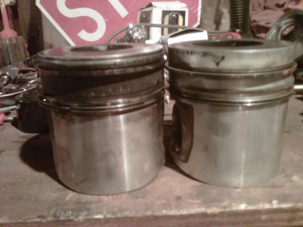
IMG00187-20111204-1448.jpg
 
Thanks Fingers.

And gettting back to the SAE paper - in terms of a competition situation, i.e., 10-15 second bursts -

Does anyone think, in a motor spinning 4500 rpm +, that a very good / thick piston crown ceramic coating could actually hurt HP by increasing charge density in the very little time it has to fill the cylinder (180 degrees crank rotation +/-)?

My gut tells says "doubtful" in this situation, but I'd change my mind if someone had some math / data that was contrary. Keeping the piston crown cooler would seem to be a very small aspect compared to everything else the intake charge sees. (cylinder walls, valve, intake runner, head deck, etc.

Essentially the coating is put there to keep the piston structure cooler and therefore stronger, but its effects on the intake charge is something that I didn't think too much about. If the thermal barrier was really getting close to ideal, the skin temp would be sky high.
 
Thank you Fingers, gave me some great things to think about.

Here is the Cummins dump truck piston I cut up, I haven't found my steel articulated piece yet though. I am not sure what horsepower rating this piston was used in, maybe around 300 I would like to believe.
Cumminspiston.jpg

Here is crown of that one, having flycuts or valve reliefs if you will.
Cumminsheavytruck.jpg

Here is a 3208 Caterpillaer piston unknown power level
0510111420.jpg

Here is a 4-53 Detroit Diesel unknown power level
0513111316a.jpg

0513111316.jpg

Here is a piston out of the old 855 Cummins big cam engine. unknown power level
0509111655.jpg
 
All the 855 pistons for the big cam engines were aluminum as far as I know, there might be some odd ball marine apps. As far as older mechanical big truck engines the rule of thumb was over 800hp and you need to run a steel top piston. Now a days it doesn't matter what the rating they are all sold with monotherms in them.

If you are looking for a 2 piece articulated piston look for a 3406E or early C15 piston.
 
Thanks Fingers.

And gettting back to the SAE paper - in terms of a competition situation, i.e., 10-15 second bursts -

Does anyone think, in a motor spinning 4500 rpm +, that a very good / thick piston crown ceramic coating could actually hurt HP by increasing charge density in the very little time it has to fill the cylinder (180 degrees crank rotation +/-)?

My gut tells says "doubtful" in this situation, but I'd change my mind if someone had some math / data that was contrary. Keeping the piston crown cooler would seem to be a very small aspect compared to everything else the intake charge sees. (cylinder walls, valve, intake runner, head deck, etc.

Essentially the coating is put there to keep the piston structure cooler and therefore stronger, but its effects on the intake charge is something that I didn't think too much about. If the thermal barrier was really getting close to ideal, the skin temp would be sky high.

I would tend to agree. The piston is moving away from the incomming intake charge and the boundary layer would increase in thickness as the air velocity slowed.
 
The crown may be moving away from the charge that is being pushed into the cylinder, however if the thick coating was doing exactly what the paper said, you have to see it as the residual temperatures in the cylinder are whats heating the intake charge mainly, however the heat residing in the crown will move to the path of the lower temperature. We have exhaust gas residuals too due to valve events.

Say we have a perfectly positioned piston decending into the bore, we have 3 ways (without water injection) we are cooling the piston, through the rings, the underside oiling or and oil gallery in the bottom of the crown structure and by the incoming charge, no bore to skirt touching. If we want to really overcome the heating effect of the residing hot cylinder gases from our burn cycle we should lower the temp of the intake air even more by means of a 'cool-can(s)' or refrigerated (similar to your A/C system) IMO. Even with high temps at IVO if we get a lower induction temp we could make up for the fresh charge expansion (lower Vol. efficiency) prior to cooling mods, R&D will be time consuming if you don't have sheetmetal and a welder etc at each power level but to control the amount of heat taken from the fresh charge (regulated by thermometer) should benefit no matter what, just the amount of benefit will have to be determined through trials.

As far as the boundary generation due to slower air speeds I think that reduction could only be nominal but yes the layer should regroup unless there is a continuous disruption. Good thoughts going around! :pop::Cheer:

It seems that oil cooling within the crown or not existant is dictated by the level of power the engine is desired to develop according to another individual I have spoken with.

SmokinCat, I have an articulated out of a 3406 somewhere, I know I do! lol I just can't find it. I am not sure if the usual keystone top rings have stayed in OEM apps or not, since we are dealing with higher speeds with the crankshaft, could there be a change from the keystone design for the top compression ring?
 
If that is really true and it has a significant effect, you would expect to see lower mass flow through the engine going from nekkid pistons to coated.

What kind of engine was this work being done on? Single-cylinder laboratory unit or real-world engine under boost pressures similar to what we see in our world?

SAE papers are generally well done but you still have to make sure what they're doing applies to what we're doing....making power with no regard for emissions.
 
A lot of great info here. I would say its more than enough to make my head hurt when thinking of all the math applied to make the #s work in engineering these parts.
 
Say we have a perfectly positioned piston decending into the bore, we have 3 ways (without water injection) we are cooling the piston, through the rings, the underside oiling or and oil gallery in the bottom of the crown structure and by the incoming charge, no bore to skirt touching. If we want to really overcome the heating effect of the residing hot cylinder gases from our burn cycle we should lower the temp of the intake air even more by means of a 'cool-can(s)' or refrigerated (similar to your A/C system) IMO. Even with high temps at IVO if we get a lower induction temp we could make up for the fresh charge expansion (lower Vol. efficiency) prior to cooling mods, R&D will be time consuming if you don't have sheetmetal and a welder etc at each power level but to control the amount of heat taken from the fresh charge (regulated by thermometer) should benefit no matter what, just the amount of benefit will have to be determined through trials.

Actual contact is not necessary for energy transfer. Heat dump from the skirt to the cylinder is through the trapped air space. (and oil!) Since the space is minimal (0.003") the energy flows rather well. (put an ice cube near your finger, but not touching, and tell me it isn't sucking heat) Depending on piston design, the skirt can account for well over half the cooling. Remember, the cylinder walls are in the 200* - 300* range with lots of water to help them absorb heat.

But... What do I know.

Id agree with this, but its fair to say the bulk of the heat ttransfer from the piston crown to the bore is through the top ring. Logically it is closer to the heat source and also is the least insulated route of transfer.

In terms of design, I guess more critical is the magnitude of required heat displacement from the crown, which will be largely be dependent on material i.e. If its a forged alloy part, a higher heat transfer rate is experienced so a cooler crown often follows, therefore there is less dependency for dissipation through the body of the piston, so a "slipper" design can be implemented. Though the level of this will be dependent on rod-length/stroke ratio.
 
Last edited:
The top ring has heat rejection problems of it's own. It is far from a cooling element for the piston.
 
If that is really true and it has a significant effect, you would expect to see lower mass flow through the engine going from nekkid pistons to coated.

What kind of engine was this work being done on? Single-cylinder laboratory unit or real-world engine under boost pressures similar to what we see in our world?

SAE papers are generally well done but you still have to make sure what they're doing applies to what we're doing....making power with no regard for emissions.

Well, I would have to say, take the paper number and search for it to see what the entire piece says, I am sure there are variances due to boosting pressure levels. Just check and double check things, being 20 years old things could have changed some too.

Yes, fingers I do agree radiation of heat is very active, but as far as the first 3 items we have within. Theres also the wrist pin and connecting rod dissipating heat as well to the oil at the con-rod bearing. I do have a question though on top ring construction, what have you seen as a good design in the higher performance applications?

Recent article
Aluminum Vs. Steel Diesel Engine Pistons - Diesel Power Magazine
 
The heat transfer is almost strictly a delta T driven event. The mass of the air charge is essentially fixed. Fuel adds ~ 5% to the mass at most. Higher chamber pressures come with higher chamber temperatures and also higher heat transfer to the pistons.
Would you say the heat produced within the chamber is somewhat proportional to heat dissipation through natural process from what you have observed of hot to cold movement Fingers?

The top ring has heat rejection problems of it's own. It is far from a cooling element for the piston.

After thinking about this and finding a piece in Robert Brady's book as far as ring materials used and info on a design used in 1995 of the T444E Navistar. First, the materials, some investigation into thses should shed some light as to how much we actually conduct heat wise through the rings.

Pg419
To meet strength, scuff and wear resistance requirements created within the combustion chamber and cylinders of high speed heavy-duty electronically controlled engines yet remain cost-effective, piston rings are available in a wide variety of materials. Rings are generally manufactured from spun cast sleeves or single-cast blanks. These include, spun-cast alloyed and heat-treated pearlitic modular graphite cast iron, ductile cast irons, spun-cast carbide malleable and flake graphite irons, carbon and high-alloyed steels, and heat-resistant nickel and cobalt alloys. Coatings to improve ring face wear from abrasives and scuffing include conventional electroplated nickel-chromium and plasma-sprayed complex chromium irons and molybdenum carbide for extreme operating conditions. Thermochemically treated chromium is generally used in top compression (fire) ring applications that require marginal lubrication. These materials also provide rapid seat-in and good oil control.

Here is the T444E on page 422
The three-ring package arrangement is also being used on lighter-duty diesel engines as well as midrange truck applications. Figure 15-44 illustrates a 1995 Navistar T444E engine gravity cast-in Ni-resist insert for improved top ring groove wear. This engine is in the 140 to 160 kw (190 to 215 hp) range with a 17.5 compression ratio V8. The ring package for this engine follows the balanced-pressure design concept; the top ring is located 9mm (.350 in.) below the piston crown. The top ring is a keystone, barrel-face design made of gravity cast ductile iron with a molybdenum-plasma facing material. The second ring is a gray iron, negative twist, taper face rectangular ring. The oil ring is a 3.335 mm (.132 in.) wide, gray iron, one-piece conformable ring with an expander spring......

I am not sure if anyone notices the ......Ni-resist insert for improved top ring wear..... as something that is more pronounced than the other information in this paragraph. I believe that is hinting that if you are running a drag car/truck (or an app ran much less time wise) tearing down often and inspecting, the use of a ni-resist attribute wouldn't be needed. One reducing the cost of the piston and slightly in weight especially when a few grams can effect your engine acceleration.

As far as the rings themselves, I am still poking around since a keystone ring just doesn't seem like a design that could be stable at high rpms in a diesel engine, but thats just my thought. Would anyone happen to know what rings the Duramax, newer Powerstrokes and Cummins light duty diesel engines use?

If someone were to use block filler, wouldn't the piston, regardless the material swell more due to less heat going to the wall and then onto coolant. I don't know the qualities of the block filler but the liquids seem to remove heat better than solids do either the water jacket or the oil gallery below the crown. I wish I had a piston of each to cut and see who uses oil cooling galleries just under the crowns in light duty mills. Hmmm....
 
Last edited:
If/When I get some time this weekend, I'll go through some of the math on heat rejection and post. Probably do it in sections so it doesn't get too long winded.

Food for thought. Though most think oil cooling galleries in pistons are there to keep the crown of the piston cooler, and they do to some extent, they are really there to protect the top most ring and land. If and when the oil does not fill the cavity, the gallery becomes a thermal break between the topmost part of the piston and the skirt causing a huge increase in temperature.
 
Thats great Fingers, reading the ICE in Theory and Practice by Charles Fayette Taylor, the topic of calculus is pretty wild. I never have thought of how the signs and equations could be posted here. I had found something on aluminum trunk pistons in Vol 2 in the engine design section, but at the present moment, I will have to post it later.

Thank you for posting everyone, its be pretty interesting thus far.
 
If I remember correctly Cummins heavy and medium duty engines (medium duty including the ISB) both used a "Positive Twist" Keystone top and intermediate ring. Keystone rings by design "promote superior combustion sealing" and also reduce the amount of particulate that ends up trapped in the oil. That is a whole different discussion.

This is from my memory and if I can find some information to support my statement, I'll post it.

For informational purposes -

As for the piston cooling, the natural gas pistons I see regulatory have a case galley underneath, in this case, piston bowl feed by a whole and cooling nozzle. The 06 5.9 im building with none re-intrentrence style pistons have this identical galley as well. The new ISX monotherm pistons used a stamped steel plate pressed into the bottom of the piston to form the galley. Maybe this is because of casting complications?

Note* another used of this oil galley is to supply oil to the oil control ring.. See the picture of the piston you cut in half, you can see the oiling holes above the piston pin. They used the cased cooling galleys in the new pistons to also lubricate the cylinder.

Hope this helps out, if at all..
 
Last edited:
Top