P Series Bosch pumps

^^^^^^ this guy is smart.....:thankyou2:

so, does that mean no more smoke and mirror's ???*bdh*:blahblah1::nail:
 
If you look at the smoke through a mirror you'll figure it out!
Now you're really confusing me. I understand the smoke and magic thing but where do the mirrors come in?

I think there was way more than smoke and mirrors involved in the cr fuel system...probably something more like juice or acid...maybe even some heavy metal. LOL
 
The rack twists the barrels with raises or lowers the spill port. Once the spill port is covered by the plunger it starts to build pressure and inject fuel.

The barrels are fixed in position. The rack is connected to the Plunger via a control unit. The control unit has an "arm" of sorts that rides in a coordinated slot in the rack. As the rack moves forward and back, it causes the control to rotate. This control unit is flat on two opposing sizes, the same as the plunger. This allows the plunger to travel up and down freely in the control unit. The control unit stays in place vertically and only rotates.

Now, with the rack all the way back (back of pump, engine, etc.) the plunger will have a vertical slot lined up with the fill port in the barrel. This creates a non-pumping situation (the fill port is never covered, so fuel is never pushed out). Just farther forward than shut-off is idle position. The plunger turns far enough so the upper and lower helix can cover the fill hole and provide additional coverage to push fuel out.

This process is the same as rack increases, the upper and or lower helix become farther apart which increases effective lift and provides more fuel pumping displacement.

Hope that helps. :Cheer:
 
Magic also happens when the rack sticks all the way forward.

People start running as if by magic.
 
I asked if the barrel had a slit up the side or something, and this is your response?


That's the job of the helix in the plunger :bang

Charles, did you even take the time to look at all the pictures in the link that I posted for you?


Obviously based on subsequent posts by others, the barrel has a hole to make fuel spillage possible. Otherwise that helix that you view as being akin to the flux capacitor of fuel injection would serve no purpose whatsoever.

I'm going to have to assume you don't actually have any real conceptual understanding of how the pumps work. And in so doing, I'm going to have to ask that you keep the word regurgitation act to yourself for a while, and let people that actually understand how things work post if they wish.

But thanks.
 
The barrels are fixed in position. The rack is connected to the Plunger via a control unit. The control unit has an "arm" of sorts that rides in a coordinated slot in the rack. As the rack moves forward and back, it causes the control to rotate. This control unit is flat on two opposing sizes, the same as the plunger. This allows the plunger to travel up and down freely in the control unit. The control unit stays in place vertically and only rotates.

Now, with the rack all the way back (back of pump, engine, etc.) the plunger will have a vertical slot lined up with the fill port in the barrel. This creates a non-pumping situation (the fill port is never covered, so fuel is never pushed out). Just farther forward than shut-off is idle position. The plunger turns far enough so the upper and lower helix can cover the fill hole and provide additional coverage to push fuel out.

This process is the same as rack increases, the upper and or lower helix become farther apart which increases effective lift and provides more fuel pumping displacement.

Hope that helps. :Cheer:


It does, but I'm going to have to look at a good picture of the plunger cuts and a barrel, as right now my mind can't figure out how rotating a uniform helical cut so that it met up with a hole in the barrel at various depths wouldn't just alter the point in time when fuel was spilled, rather than the quantity injected.

(And yes I've looked at every last picture posted in this entire thread. More than once...)

Like....

With it rotated with the rack full rear, where the vertical tip off the end of the helical portion is located it would do this.


--------------------

Full spill obviously.


And as you turn it forward it might do this.

---------------xxxxx

Where x is pressure built, nozzle needles popping and fuel being injected.


But what I can't figure out, is how when turned farther you don't get this:

----------xxxxx------

???


Seems like by rotating a helical cut you'd just change the timing of when the plunger cut met with, and then passed by the spill port in the barrel.


Just like a split shot "pilot" injection on a Heui injector when the spill port groove in the plunger lines up with the hole in the barrel.
 
Once the helix passes the fill port all fuel remaining in the barrel is directed through the helix back through the fill port into the pump case.
 
It does, but I'm going to have to look at a good picture of the plunger cuts and a barrel, as right now my mind can't figure out how rotating a uniform helical cut so that it met up with a hole in the barrel at various depths wouldn't just alter the point in time when fuel was spilled, rather than the quantity injected.

Seems like by rotating a helical cut you'd just change the timing of when the plunger cut met with, and then passed by the spill port in the barrel.

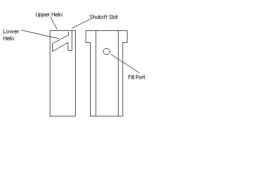
Check this quick drawing out for better understanding. The upper helix is flat and doesn't vary timing in my picture. Some pumps have an upper helix as well (215 pumps) that do vary timing, but for ease of explaining just assume we're talking about a flat top plunger pump (160, 175, 180, etc).

Initial injection doesn't change, but duration does change as more fuel is injected (obviously).

bp.jpg
 
Once the helix passes the fill port all fuel remaining in the barrel is directed through the helix back through the fill port into the pump case.

I would think that as it passed the spill port (fill port) that it would reseal on the uncut portion of the plunger, and all remaining stroke would be forced out to the injector.

Like this...

As the stroke begins and the helix is not in line with the fill port it would be expelling fuel to the injector, then as the helix cut crossed over the fill port it would spill fuel back to the case, and then as the lower edge of the helix cross beyond the fill port injection would resume.

xxxxxx----------xxxxxx


I would have expected the cut in the plunger to look like this:

2827594010082519711S600x600Q85.jpg
 
Check this quick drawing out for better understanding. The upper helix is flat and doesn't vary timing in my picture. Some pumps have an upper helix as well (215 pumps) that do vary timing, but for ease of explaining just assume we're talking about a flat top plunger pump (160, 175, 180, etc).

Initial injection doesn't change, but duration does change as more fuel is injected (obviously).

bp.jpg


I think it's pretty cool that we both resorted to paint...

:hehe:


But what I can't quite get is why the little triangle formed between the full stroke end of the shut down slot, and the full stroke end of the helix when the rack is full forward doesn't start injection again? That triangle will reseal the fill port and remaining fuel would be injected.

What am I missing there?

Look at the plunger my mind would expect to see here in my drawing. Mine's the one on the right without that triangle of area to reseal the fill port.
 
I would think that as it passed the spill port (fill port) that it would reseal on the uncut portion of the plunger......................................I would have expected the cut in the plunger to look like this:

2827594010082519711S600x600Q85.jpg

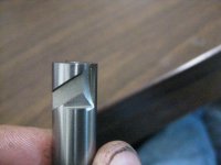
You got me thinking so I went out to my box of parts and got my flashlight...with light shining in the fill port and the plunger all the way up, with the bottom of the helix covering as much of the fill port as is possible I could still see light entering the helix, the space was very small but sufficient to prevent pressure build. I've seen custom cut plungers look exactly like your idea of how they should look...
 
You got me thinking so I went out to my box of parts and got my flashlight...with light shining in the fill port and the plunger all the way up, with the bottom of the helix covering as much of the fill port as is possible I could still see light entering the helix, the space was very small but sufficient to prevent pressure build. I've seen custom cut plungers look exactly like your idea of how they should look...


I would have expected the light would have been cut off again at full stroke with the plunger turned toward idle speed.

Otherwise I can't figure out why the "shut down" slot needs to extend so far down in the first place.
 
One thing I missed or forgot to mention, there is a helix cut in both sides of the plunger, the one has material cut out at the bottom the other does not...there is also two fill ports.
 

Attachments

  • IMG_0084.JPG
    IMG_0084.JPG
    43.4 KB · Views: 102
I would have expected the light would have been cut off again at full stroke with the plunger turned toward idle speed.

Otherwise I can't figure out why the "shut down" slot needs to extend so far down in the first place.

My rendering was a very rough one...the bottom helix is cut wider than my picture and doesn't allow complete spill port coverage after the initial injection. The shutoff slot is cut quite a ways down on most plungers...probably just a machining process because it isn't necessarily needed.
 
So if you want to adjust pump output balance you loosen the barrel bolts and turn the barrel (altering the helix to fill port relationships) until each cylinder moves the same?

So when I see reference to "turning the barrels" is that people rotating them so that the fill ports contact the helices at increased plunger stroke depths, all else constant?

And if so, how do these people just assume there will still be good balance with all the barrels bottomed out this way?

Do they just assume perfection in machine work between all parts?


Speaking of which.... as if machining a good P&B weren't hard enough, cutting freakin slots in the plungers and then not having sealing problems at the edges of those slots, seems crazy.
 
Charles, one more thing that will change the helix to fill port relation ship is the barrel shims. The shims will usually vary in thickness, even on a new pump.

This shims are located under the barrel, two per barrel, one under each side, they are held in place when the nuts are tightened.
 
Back
Top