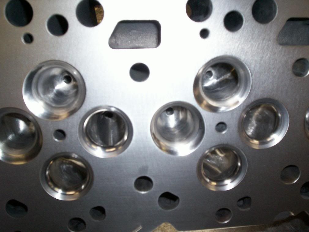
Several problems with this milling of the head, if you take material off the deck this lessens the materal that is necessary to achieving even clamping load.
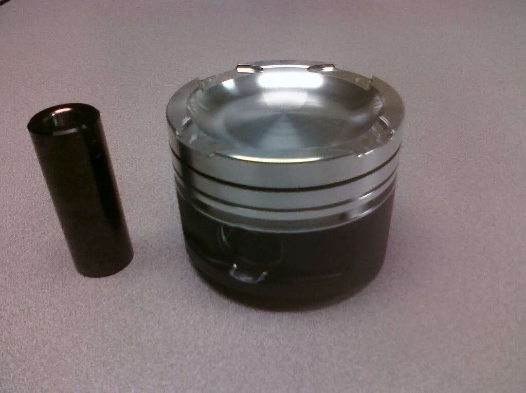
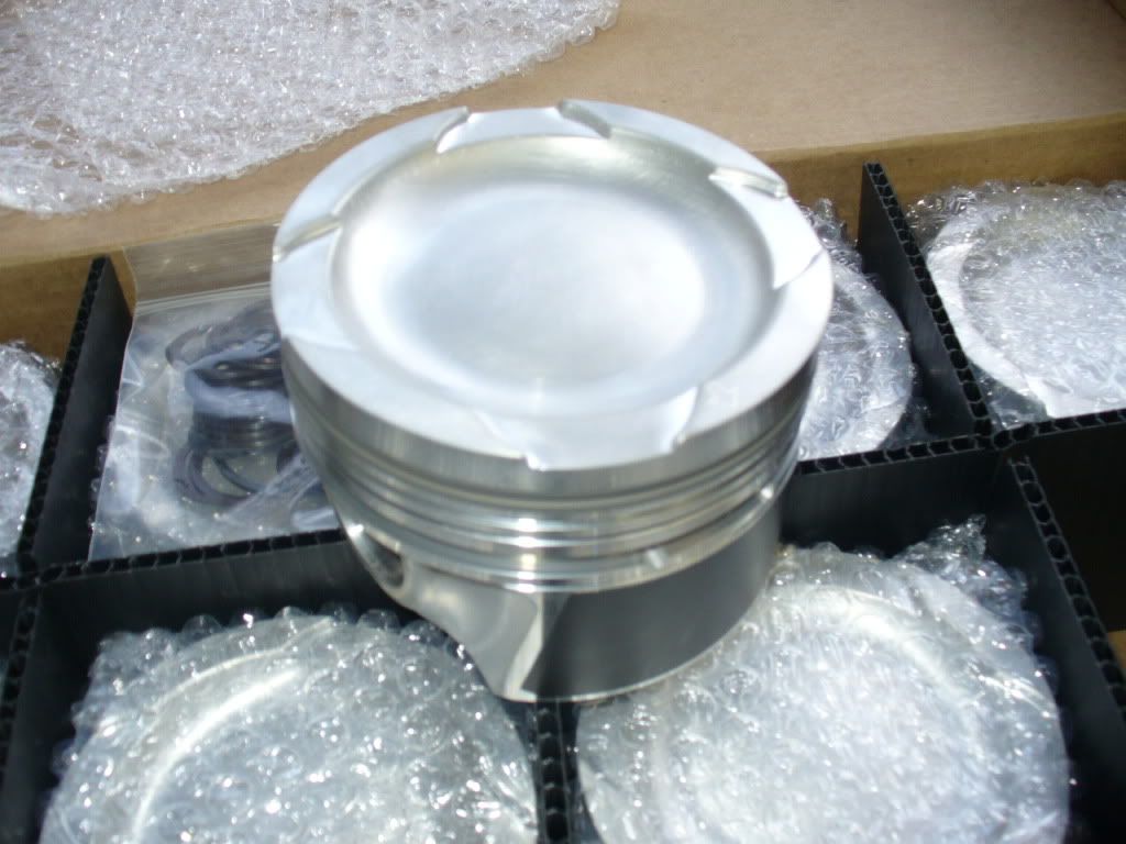
The placement of the nozzle is achieved by changing the piston bowl. I use a very shallow bowl design similar to the Dmax pistons pictures here. before someone takes about the expense of pistons , if you at this level and not spending another $1200 to $1500 on a good set of pistons then you not going to be competitive.
The particular aspect of combustion chamber and injector relationship is critical in exposing the fuel plume to as much air as soon as possible. This will utilize the available fuel more efficiently.
Excess fuel or late combustion cycle fueling absorbs heat, and causes late burn, leading to high egt’s. The small bowl design of the older Cummins pistons are designed for emissions. If you will look at the progression of pistons designs over the years it’s corresponds to the pressure of the injection systems.
Next to airflow and cam design. The low lift flow is great if you head dosen't almost double airflow at higher lifts.
Milling the heads to unshrowds the valves causes another problem, in that the air is defused in 360 degrees, and impinges on the cylinder bore. The better way to do this is by working the area around the valves in to a chamber.
There is a lot of potential available airflow in valve seat angles. The stock 30 degree seat is advantageous to low lift air flow. Below .200 lift
The high valve seat angle dramatically open up air flow above .200 lift
Now to well engineer cam design, and how it relates to maximizing airflow, in both maximum effort engine programs, and street performance.
First to clear up the methods on cam measurements and cam design, something I have been involved with for the last 25 years
.
All cam numbers are taken from the tappet, end of story .
The rocker systems , and corresponding ratio’s on any engine is a variable that is taken in account , in acceleration rates at the valve , but again the cam numbers are allalways taken at the tappet, this is the way that every cam designer has used for 50 years .
Next let’s move on to tappet diameter and relationship to cam numbers. the three tappets are the 1.5 common rail lifter, the 1.3 24 valve lifter, and the .9 12 valve lifter.
The lifter diameter bears zero relationship to the duration numbers if the cam has low enough acceleration ramps to utilize the smaller lifter.
When I design a cam profile, I look at the diameter of lifter needed to utilize that profile, if a .900 lifter is all that is needed, then a bigger lifter will have zero effect.
If a cam profile has slow enough ramps to utilize a .900 lifter it would be of little use in any performance application.
Now to what happens if you use too small of a lifter for a given profile, the results would be almost immediate destruction as the cam lobe rides on the edge of the lifter.
My entire ranges of street cams require a minimum of 1.27 lifter diameter, to safely cover the cam profile. My race profiles utilize a lot more of the lifter.
The design parameters of a race cam program, in any engine look only at 4 events. and more than just numbers at .050 .
Diesel performance applications have certain parameters that are set in stone. Overlap (when both valves are open at the same time) is never good in any application where a turbo supercharger is being used. .
The next event is closure of the intake valve. When a given engine combination is running, the air flow in to the cylinder is still moving when most cams are shutting the intake valve. the higher the rpm the more this comes in to play
With volumetric efficiently in the tipical diesel engine in the low 40 % at higher rpm’s the amount of airflow to be gained is dramatic by keeping open the intake a lot longer than most do .
Next is rocker ratio, and cam lobe lift .
On our the new common rail 2.6 engines programs, we are using a 1.85 ratio and .335 lobe lift, this on a 60 mm cam. This larger cam core is almost a quarter of a inch in diameter bigger then stock Cummins. This allows me to design a cam profile that will mover the valve at unheard of rates, and still maintain valve train control.
The high lift numbers, move huge amounts of air for a long time, if the maximum valve is lifted .625, and I do lift them that much, then the valve dwell at .400, .450 ,500 , .550 is much longer .
As far as number and people giving those numbers out there are so many numbers on a cam that are extremely meaningful, and would take hours of conversation to explain them to most cam consumer. I give all the number that are asked for , spend a lot of time helping pick the best profile for a given aplacation
one thing to concider, Just because a cam has bigger numbers at .050 doesn’t mean it’s a bigger cam. There are .200 numbers, acceleration rates, pre ramps and many more aspects. On my race cams I use a pre ramp to help crack open the exhaust cam event to minimize stress on the valve train. Bottom line if you trust you cam designer, then talk to him, and use what he knows.


