VP44 Standalone ECU Project

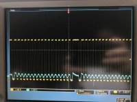
I used an LM741 to amplify the signal coming out of the pump sensor and AC coupled the amplified output into a zero crossing ASIC that’s made to read VR sensors, the output is in the pic below.
E93C89C9-0E91-4E93-8A28-0F86FF0F4CEC.jpg

That’s exactly what I’ve been after from the start, I believe this is a signal I can process consistently. Only issue is that the ASIC I’m using is hard to come by. I should’ve ordered a few of those ASICs Brandon mentioned on the first page, now that I have a handle on what’s going on I see why it was recommend so thanks for that :Cheer: Learned a few things along the way so I’ve got some ideas on how to improve upon what I’ve got now, just need parts for it.

Also put together a basic low side driver circuit for the fuel solenoid with a fly back diode across the output. Seems to control it easily, I’m able to pwm the solenoid relatively fast, we’ll see if it’s accurate enough. I’ll have to do some testing to make sure there’s no issues with heat long term.
AC32DB3D-3A86-4219-9ECC-A2D6E89B82D8.jpg
 
I used an LM741 to amplify the signal coming out of the pump sensor and AC coupled the amplified output into a zero crossing ASIC that’s made to read VR sensors, the output is in the pic below.

View attachment 72520

That’s exactly what I’ve been after from the start, I believe this is a signal I can process consistently. Only issue is that the ASIC I’m using is hard to come by. I should’ve ordered a few of those ASICs Brandon mentioned on the first page, now that I have a handle on what’s going on I see why it was recommend so thanks for that :Cheer: Learned a few things along the way so I’ve got some ideas on how to improve upon what I’ve got now, just need parts for it.

Also put together a basic low side driver circuit for the fuel solenoid with a fly back diode across the output. Seems to control it easily, I’m able to pwm the solenoid relatively fast, we’ll see if it’s accurate enough. I’ll have to do some testing to make sure there’s no issues with heat long term.

View attachment 72521


Very interesting, and look forward to seeing what the outcome is.
 
You're welcome! No telling how many ICs were sacrificed before I came to that knowledge. LOL
 
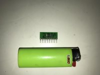
Didnt realize how tiny these ASICs were until they showed up, I ordered some surfboards to put them on so I could plug em into the breadboard.

413707A4-2B20-4E7D-A8E2-8A56E9B5424C.jpg

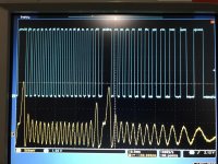
Haven’t spent a ton of time with them but first results look very promising, real clean signal coming out. Using a MAX9925 in this capture, thanks again Brandon for the recommendation. I need to work on the signal coming from the pump sensor a little more but it’s getting close.

DA8765F3-72FA-4502-B9D9-2AD07DD513C7.jpg
 
Instead of re-reading everything, if this come to fruition as intended, it would allow for complete vp44 engine swaps? Such as into a '70s pickup?

Sent from my SM-G960U using Tapatalk
 
Between this thread and all of the stuff joefarmer has posted over the years, I feel really dumb.

Sent from my SM-G960U using Tapatalk
 
Hahaha, part of the reason not to re-read it yet, it's all over my head!

Sent from my SM-G960U using Tapatalk
 
Instead of re-reading everything, if this come to fruition as intended, it would allow for complete vp44 engine swaps? Such as into a '70s pickup?

Sent from my SM-G960U using Tapatalk

If everything works out the way I hope then it would work for swaps and such. Although this is already possible using the stock Cummins ECM and a few wires from the Dodge harness.
 
If everything works out the way I hope then it would work for swaps and such. Although this is already possible using the stock Cummins ECM and a few wires from the Dodge harness.

Following along as I think this stuff is cool as hell.

To me VP trucks are just as easy to get running as P-Pump trucks. Speical standalone like whats done in a swap. You need power and ground and TPS input. The rest can be left alone.
 
It's just that there seems to be a steady rate of failed ECM's, with replacements being kinda hit or miss. So kinda hoping this could turn into a viable alternative.

Sent from my SM-G960U using Tapatalk
 
It really all comes down to money.
Is the average Joe going to want to sink even $1000 into an updated ECM for an 18 to 21 year old truck?

It's hard enough to get people to pay $400 for a lower miles used one, for a truck they have to have running every day.

Even so, I think the best course is to get a viable replacement ECM available, to address the ECM supply issue.
Especially since the pump workings, and the pump module itself, seem to be the manageable part.

Mark.
 
Didnt realize how tiny these ASICs were until they showed up, I ordered some surfboards to put them on so I could plug em into the breadboard.

View attachment 72576

Haven’t spent a ton of time with them but first results look very promising, real clean signal coming out. Using a MAX9925 in this capture, thanks again Brandon for the recommendation. I need to work on the signal coming from the pump sensor a little more but it’s getting close.

View attachment 72575
I'm happy they worked so well! That's a very nice solder job. My first hand solder with 0.50 pitch did not look like that. LOL
 
When I get time one of these nights I need to see how the new ASICs handle the sensor signal as it is, if I could avoid amplifying the signal that'd be ideal. Either way I need to start doing some calculations to make sure the sensor will be read accurately over the whole rpm range.

Haven't had a ton of time to mess with things lately, going to be moving out in the next month so I'm hoping that'll free up some time once I get all settled in.
 
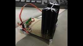
Turns out that ASIC is able to read the signal coming out of the pump pretty accurately on its own, probably would've saved a couple months if I tried that right off the start but I learned a few things along the way. I put the circuit together on a protoboard so I could clean things up and get rid of my breadboard mess. Hooked it up to a function generator and fed in a signal similar to the pump sensors output, the circuit was able to read it across the whole rpm range without issue. I'll have to find a way to spin the pump at around 2500rpm to make sure it handles that signal alright, don't think that part of the circuit will be a limiting factor though. That mosfet/heatsink on the right is going to end up being my low side driver for the fuel solenoid. Just need to clean up a few things on the board and wire it to the arduino then it's time to start writing code.
sensor interface.jpg
 
It really all comes down to money.
Is the average Joe going to want to sink even $1000 into an updated ECM for an 18 to 21 year old truck?

It's hard enough to get people to pay $400 for a lower miles used one, for a truck they have to have running every day.

Even so, I think the best course is to get a viable replacement ECM available, to address the ECM supply issue.
Especially since the pump workings, and the pump module itself, seem to be the manageable part.

Mark.

no need for any boxes and full control? count me in, this is awesome and I will order the first
 
Been finding it hard to make time to work on this when the weathers so nice, I'll be slowly picking away at it over the summer but I'm not expecting big progress anytime soon. I'm sure things will pick back up when it cools down.
 
Getting back into this now that it's too cold for the garage. Learned a few things on the hardware side since I last left off.

The circuit that reads the pump sensor has been working great while the pump is spinning but after a second or so of inactivity I'm starting to see a lot of noise on the output. Guessing there's some sort of oscillation due to the conditioning circuit I'm using, got a few ideas to fix it.

For controlling the fuel solenoid my initial plan was just to use a MOSFET as a low side driver and run it at full current for the whole injection event, not ideal but I'm sure it'd work initially. Started looking into how and why peak and hold circuits are used for low impedance injectors like this. Found an off the shelf ASIC that looks like it'll do exactly what I need, fires the solenoid with full current, after the threshold is reached the driver backs off and holds it open with 1/4 of the initial current. Kind of similar to how a ppump fuel shutoff solenoid works but this one is only using a single coil. Should be easier on everything and also give a quicker and cleaner end of injection.
Sounds like fun! What IC is it?
 
It is cool to see this go down but on a serious note if you plan to make this a money making venture once it is all complete I wouldn't show too much...

A lot of companies in this industry have zero morals and would gladly steal the fruits of your labor.

Keep kicking azz though it is impressive!
 
Back
Top