You are using an out of date browser. It may not display this or other websites correctly.
You should upgrade or use an alternative browser.
You should upgrade or use an alternative browser.
New Pro Stock Diesel build - 2 D Max
- Thread starter Michael
- Start date
Michael
Comp Diesel Sponsor
- Joined
- Apr 25, 2006
- Messages
- 3,411
Thanks for the comments!
Episode 23:
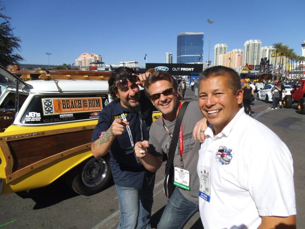
Before I get too wrapped up in this update, I have to throw out a pic of something I have been looking forward to a long time, my daughter and I managed to both win at the same event (and I also got a perfect light during qualifying, earning me the #1 spot and a T-shirt).
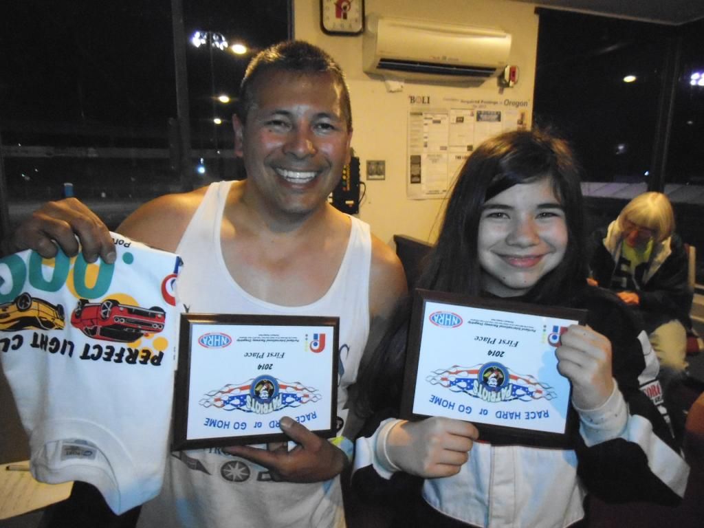
Yes, I know the plaques and shirt are being held upside down, it was my daughter's idea to make the photo more interesting.
The general theme of this update is that there have been more cerebral than physical accomplishments lately. As I approached some of the remaining details of this chassis I decided to spring for the 2-book set from Jerry Bickel Race Cars covering chassis construction. I considered buying them before, but IIRC they were close to $400 for the two books. They eventually lowered the price AND had a sale, so I picked them up for $120.
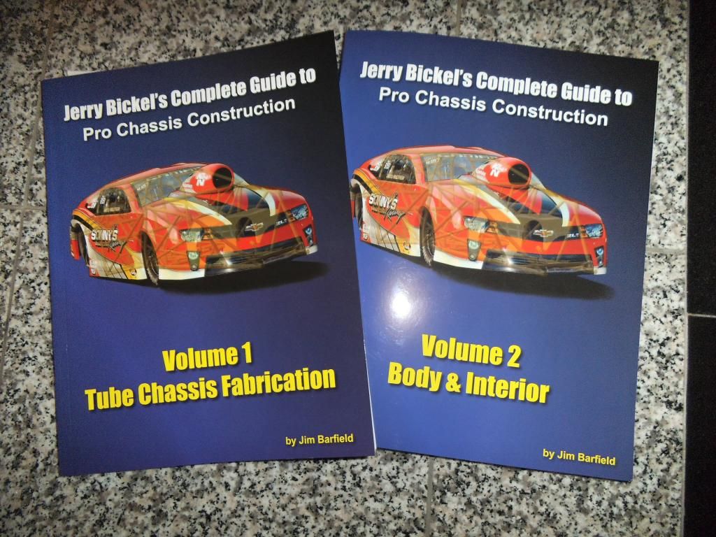
A large portion of the books covers the weird little details that I had to learn for myself and documented in this build, such as drilling pressure relief holes. They do give a lot of tips on areas I still have to do, like brake pedal and master cylinder mounting, and interior tinwork.
Speaking of brakes, I picked up a couple of master cylinders (plus a spare to keep in the trailer).

Most of the aftermarket braking companies use master cylinders based on the Chysler design they used on their mini vans and some pickups. I just bought Raybestos versions of the Chrysler parts.
I resurrected the 3D solid CAD model of the race truck so I could figure out where to place a number of components.
I started by adding some gussets to triangulate the firewall. This is a critical area, as this is where the torsional load from the drivetrain is transmitted into the chassis. However, I still needed to leave plenty of room for the up-pipes to pass through and up to the high pressure turbo.
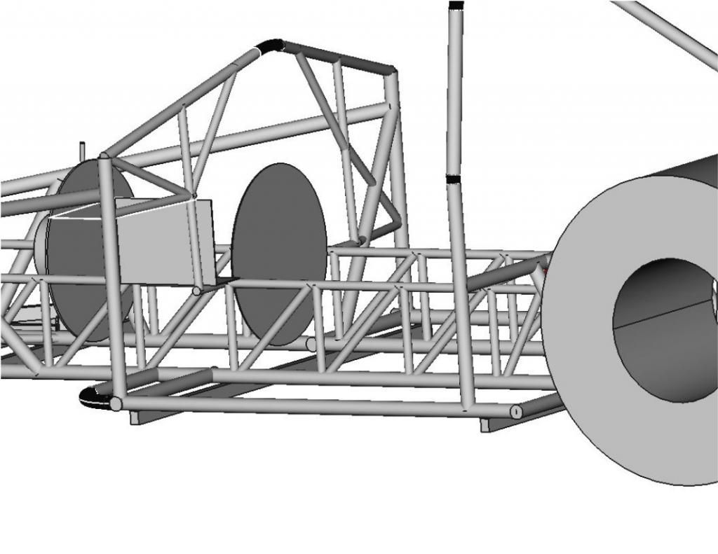
Next up I needed to figure out the angle and height of the engine/transmission combination. The overall goal is to aim the output of the transmission directly at the yoke of the rearend. I also wanted enough ground clearance to use a standard Duramax lower oil pan. This required a 2.9° downward angle in the chassis.
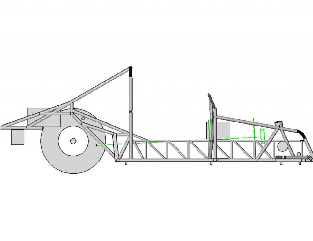
Next up I needed to model the outside surfaces of the transmission, so I could figure out how to build the tunnel and the transmission crossmember. I just simplified the shapes into stepped cylinders and a partial donut shape for the bellhousing.
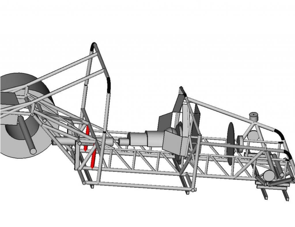
I was worried about how I was going to squeeze the fuel cell and dual batteries in the back, but eventually worked out a plan.
I originally planned to have the transmission mount come up from the existing floor crossmembers, so I added them to the model:
I ended up deciding on a simple additional crossmember to go between a pair of double frame rail uprights. Since there is not a significant load on the tail of the transmission (the torsional load is carried by the midplate), this can be a lightweight crossmember.
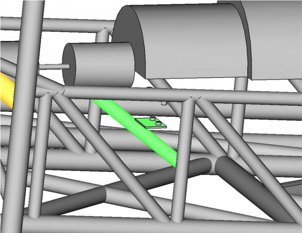
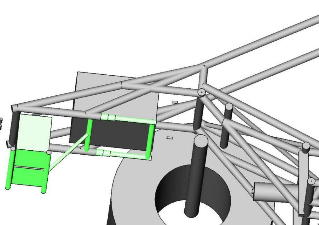
One of the next key items was figuring out how the brake pedals were going to mount. I finally decided on a stationary shaft which would be clamped to the chassis, with each pedal having roller needle bearings where it rides on the shaft. I can use simple spacers to move the pedals side to side until I am happy with their position.
My plan is to hook the left pedal up like a normal brake system, and the right pedal will be dedicated to the 2nd set of rear brake calipers. When I am building boost before bumping into the beams I can straddle both pedals with my left foot, getting as much braking force as possible.
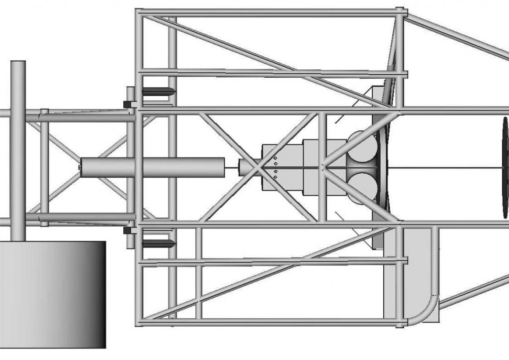
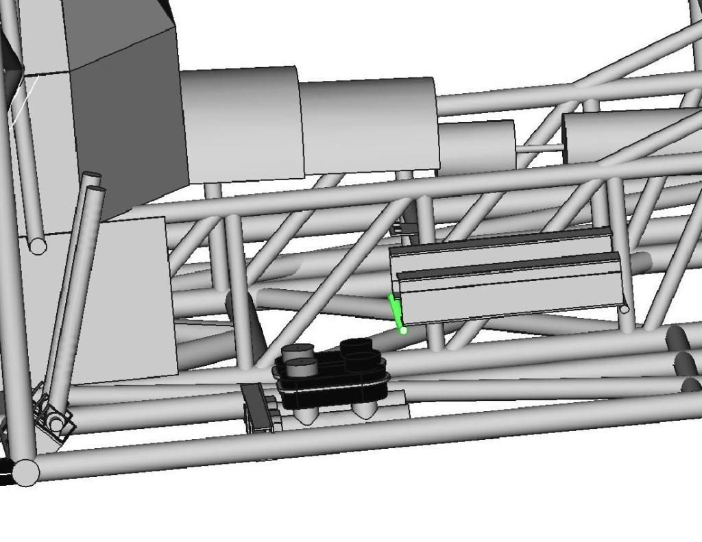
Probably the single item in the build that I put the most detail into for the CAD model was the master cylinder. With its complex shapes and the tight fit with the floor crossmembers I figured I needed all the detail I could get.
Once those were positioned I designed a crossmember to support them. I tried two versions, one was made from 1" x 1.75" rectangular tubing with cutouts, but the final version is using 0.125" plate stock. I ran the calculations for which one would be stronger, and this one won out (although they were close). I figured this one would be easier to build as well.
All of this CAD work makes me want to get my hands dirty on the real chassis! I added two more diagonals to support the upper strut mounts, and to tie into the front engine mount plate (this was another reason to get that CAD work done so I could figure out where that plate would end up).
Once those tubes were fully welded I pressed the spherical bearings back in and reassembled the steering, so I could fine tune the steering rack position and minimize the bump steer.
At this point I realized that part of the jig was hanging up the struts and preventing them from fully extending. My previous "success" at finding the optimum rack position turned out to need some fine tuning. Once I removed the jig section that was interfering, I had more front end travel to contend with!

With this additional travel I had more potential toe-in movement (bump steer) than I thought. I ended up fine tuning the rack position and getting it even better than the "short stroked" result I had before! Total toe-in change through the full travel range is now 0.02" per side, and through the main travel range it is zero!
I was hoping to have the steering finished in the chassis and the rearend at least temporarily mounted, to have as a display at this weekend's NHRDA Pacific Coast Diesel Nationals Presented by ISSPRO (yeah, that is a mouthful to say OR type). However, I decided to keep focus on the build rather than trying to get it off the jig and out to the track. Don't let that stop you from coming out to Woodburn Dragstrip on June 28th to see a great show of diesel racing and sled pulling! There will also be a lunch served compliments of ISSPRO. Hope to see you there!

Episode 23:
Before I get too wrapped up in this update, I have to throw out a pic of something I have been looking forward to a long time, my daughter and I managed to both win at the same event (and I also got a perfect light during qualifying, earning me the #1 spot and a T-shirt).
Yes, I know the plaques and shirt are being held upside down, it was my daughter's idea to make the photo more interesting.
The general theme of this update is that there have been more cerebral than physical accomplishments lately. As I approached some of the remaining details of this chassis I decided to spring for the 2-book set from Jerry Bickel Race Cars covering chassis construction. I considered buying them before, but IIRC they were close to $400 for the two books. They eventually lowered the price AND had a sale, so I picked them up for $120.
A large portion of the books covers the weird little details that I had to learn for myself and documented in this build, such as drilling pressure relief holes. They do give a lot of tips on areas I still have to do, like brake pedal and master cylinder mounting, and interior tinwork.
Speaking of brakes, I picked up a couple of master cylinders (plus a spare to keep in the trailer).
Most of the aftermarket braking companies use master cylinders based on the Chysler design they used on their mini vans and some pickups. I just bought Raybestos versions of the Chrysler parts.
I resurrected the 3D solid CAD model of the race truck so I could figure out where to place a number of components.
I started by adding some gussets to triangulate the firewall. This is a critical area, as this is where the torsional load from the drivetrain is transmitted into the chassis. However, I still needed to leave plenty of room for the up-pipes to pass through and up to the high pressure turbo.
Next up I needed to figure out the angle and height of the engine/transmission combination. The overall goal is to aim the output of the transmission directly at the yoke of the rearend. I also wanted enough ground clearance to use a standard Duramax lower oil pan. This required a 2.9° downward angle in the chassis.
Next up I needed to model the outside surfaces of the transmission, so I could figure out how to build the tunnel and the transmission crossmember. I just simplified the shapes into stepped cylinders and a partial donut shape for the bellhousing.
I was worried about how I was going to squeeze the fuel cell and dual batteries in the back, but eventually worked out a plan.
I originally planned to have the transmission mount come up from the existing floor crossmembers, so I added them to the model:
I ended up deciding on a simple additional crossmember to go between a pair of double frame rail uprights. Since there is not a significant load on the tail of the transmission (the torsional load is carried by the midplate), this can be a lightweight crossmember.
One of the next key items was figuring out how the brake pedals were going to mount. I finally decided on a stationary shaft which would be clamped to the chassis, with each pedal having roller needle bearings where it rides on the shaft. I can use simple spacers to move the pedals side to side until I am happy with their position.
My plan is to hook the left pedal up like a normal brake system, and the right pedal will be dedicated to the 2nd set of rear brake calipers. When I am building boost before bumping into the beams I can straddle both pedals with my left foot, getting as much braking force as possible.
Probably the single item in the build that I put the most detail into for the CAD model was the master cylinder. With its complex shapes and the tight fit with the floor crossmembers I figured I needed all the detail I could get.
Once those were positioned I designed a crossmember to support them. I tried two versions, one was made from 1" x 1.75" rectangular tubing with cutouts, but the final version is using 0.125" plate stock. I ran the calculations for which one would be stronger, and this one won out (although they were close). I figured this one would be easier to build as well.
All of this CAD work makes me want to get my hands dirty on the real chassis! I added two more diagonals to support the upper strut mounts, and to tie into the front engine mount plate (this was another reason to get that CAD work done so I could figure out where that plate would end up).
Once those tubes were fully welded I pressed the spherical bearings back in and reassembled the steering, so I could fine tune the steering rack position and minimize the bump steer.
At this point I realized that part of the jig was hanging up the struts and preventing them from fully extending. My previous "success" at finding the optimum rack position turned out to need some fine tuning. Once I removed the jig section that was interfering, I had more front end travel to contend with!
With this additional travel I had more potential toe-in movement (bump steer) than I thought. I ended up fine tuning the rack position and getting it even better than the "short stroked" result I had before! Total toe-in change through the full travel range is now 0.02" per side, and through the main travel range it is zero!
I was hoping to have the steering finished in the chassis and the rearend at least temporarily mounted, to have as a display at this weekend's NHRDA Pacific Coast Diesel Nationals Presented by ISSPRO (yeah, that is a mouthful to say OR type). However, I decided to keep focus on the build rather than trying to get it off the jig and out to the track. Don't let that stop you from coming out to Woodburn Dragstrip on June 28th to see a great show of diesel racing and sled pulling! There will also be a lunch served compliments of ISSPRO. Hope to see you there!
Michael
Comp Diesel Sponsor
- Joined
- Apr 25, 2006
- Messages
- 3,411
Thanks for the comments!
Episode 23:
Before I get too wrapped up in this update, I have to throw out a pic of something I have been looking forward to a long time, my daughter and I managed to both win at the same event (and I also got a perfect light during qualifying, earning me the #1 spot and a T-shirt).
Yes, I know the plaques and shirt are being held upside down, it was my daughter's idea to make the photo more interesting.
The general theme of this update is that there have been more cerebral than physical accomplishments lately. As I approached some of the remaining details of this chassis I decided to spring for the 2-book set from Jerry Bickel Race Cars covering chassis construction. I considered buying them before, but IIRC they were close to $400 for the two books. They eventually lowered the price AND had a sale, so I picked them up for $120.
A large portion of the books covers the weird little details that I had to learn for myself and documented in this build, such as drilling pressure relief holes. They do give a lot of tips on areas I still have to do, like brake pedal and master cylinder mounting, and interior tinwork.
Speaking of brakes, I picked up a couple of master cylinders (plus a spare to keep in the trailer).
Most of the aftermarket braking companies use master cylinders based on the Chysler design they used on their mini vans and some pickups. I just bought Raybestos versions of the Chrysler parts.
I resurrected the 3D solid CAD model of the race truck so I could figure out where to place a number of components.
I started by adding some gussets to triangulate the firewall. This is a critical area, as this is where the torsional load from the drivetrain is transmitted into the chassis. However, I still needed to leave plenty of room for the up-pipes to pass through and up to the high pressure turbo.
Next up I needed to figure out the angle and height of the engine/transmission combination. The overall goal is to aim the output of the transmission directly at the yoke of the rearend. I also wanted enough ground clearance to use a standard Duramax lower oil pan. This required a 2.9° downward angle in the chassis.
Next up I needed to model the outside surfaces of the transmission, so I could figure out how to build the tunnel and the transmission crossmember. I just simplified the shapes into stepped cylinders and a partial donut shape for the bellhousing.
I was worried about how I was going to squeeze the fuel cell and dual batteries in the back, but eventually worked out a plan.
I originally planned to have the transmission mount come up from the existing floor crossmembers, so I added them to the model:
I ended up deciding on a simple additional crossmember to go between a pair of double frame rail uprights. Since there is not a significant load on the tail of the transmission (the torsional load is carried by the midplate), this can be a lightweight crossmember.
One of the next key items was figuring out how the brake pedals were going to mount. I finally decided on a stationary shaft which would be clamped to the chassis, with each pedal having roller needle bearings where it rides on the shaft. I can use simple spacers to move the pedals side to side until I am happy with their position.
My plan is to hook the left pedal up like a normal brake system, and the right pedal will be dedicated to the 2nd set of rear brake calipers. When I am building boost before bumping into the beams I can straddle both pedals with my left foot, getting as much braking force as possible.
Probably the single item in the build that I put the most detail into for the CAD model was the master cylinder. With its complex shapes and the tight fit with the floor crossmembers I figured I needed all the detail I could get.
Once those were positioned I designed a crossmember to support them. I tried two versions, one was made from 1" x 1.75" rectangular tubing with cutouts, but the final version is using 0.125" plate stock. I ran the calculations for which one would be stronger, and this one won out (although they were close). I figured this one would be easier to build as well.
All of this CAD work makes me want to get my hands dirty on the real chassis! I added two more diagonals to support the upper strut mounts, and to tie into the front engine mount plate (this was another reason to get that CAD work done so I could figure out where that plate would end up).
Once those tubes were fully welded I pressed the spherical bearings back in and reassembled the steering, so I could fine tune the steering rack position and minimize the bump steer.
At this point I realized that part of the jig was hanging up the struts and preventing them from fully extending. My previous "success" at finding the optimum rack position turned out to need some fine tuning. Once I removed the jig section that was interfering, I had more front end travel to contend with!
With this additional travel I had more potential toe-in movement (bump steer) than I thought. I ended up fine tuning the rack position and getting it even better than the "short stroked" result I had before! Total toe-in change through the full travel range is now 0.02" per side, and through the main travel range it is zero!
I was hoping to have the steering finished in the chassis and the rearend at least temporarily mounted, to have as a display at this weekend's NHRDA Pacific Coast Diesel Nationals Presented by ISSPRO (yeah, that is a mouthful to say OR type). However, I decided to keep focus on the build rather than trying to get it off the jig and out to the track. Don't let that stop you from coming out to Woodburn Dragstrip on June 28th to see a great show of diesel racing and sled pulling! There will also be a lunch served compliments of ISSPRO. Hope to see you there!
biged681985
Arklahoma Bombers
- Joined
- Mar 12, 2008
- Messages
- 306
the build looks great, keep up the good work.
Michael
Comp Diesel Sponsor
- Joined
- Apr 25, 2006
- Messages
- 3,411
I know, I need to put out an update! Unfortunately I haven't made as much progress recently as I had hoped, between some OEM projects, attending the World Finals, and prep for SEMA! I need to dig through my photos and put together an update, should have one done soon.
Michael
Comp Diesel Sponsor
- Joined
- Apr 25, 2006
- Messages
- 3,411
Episode 24:
Sorry for the lack of updates, too many things going on between work and other racing, but finally getting more time on the race truck.
First off, a belated "Thank You" to all who attended the Pacific Coast Diesel Nationals Presented by ISSPRO! While we had scorching heat in prior years, this time we had torrential downpours, but somehow squeezed in the racing and sled pulling between rainstorms. We still had a huge crowd of spectators who braved the rain to cheer on the competitors.
A few details on the other items:
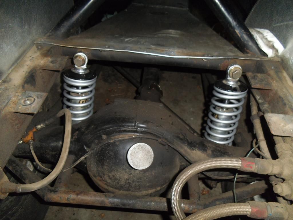
My Vega, which has always hooked really well (once I had the suspension all dialed in) suddenly started spinning the tires badly, and it turned out to be the original Koni shocks finally getting worn out. I picked up a set of QA1 double adjustable shocks and got it working well again. Just as I was fine-tuning the new shocks, it suddenly started spinning again. I was able to fine tune it and pick some ET back up, only to discover the slicks were down to the cords! I guess the suspension is REALLY working well to be able to hook up with cords showing!
My next fiasco was at a race with a really bad crosswind at the top end of the track, it ripped the scoop off on one pass, and blew the driver's window out on another! Weird crap to be happening at 147+ mph! A couple other cars had their side windows blown out too, including one with original glass that made a huge mess on the track.
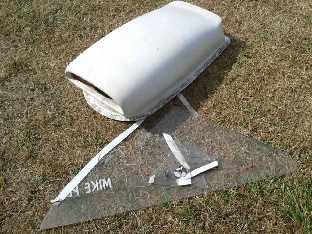
I ended up trading some parts for a complete Vega hood with scoop, and made a new side window.
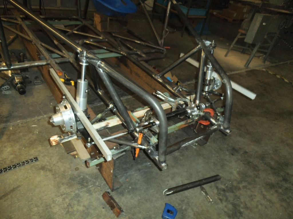
Back to the race truck, I started working on the steering mount crossmember, which was positioned at a weird compound angle (and offset from center) of the diagonal strut support bars.
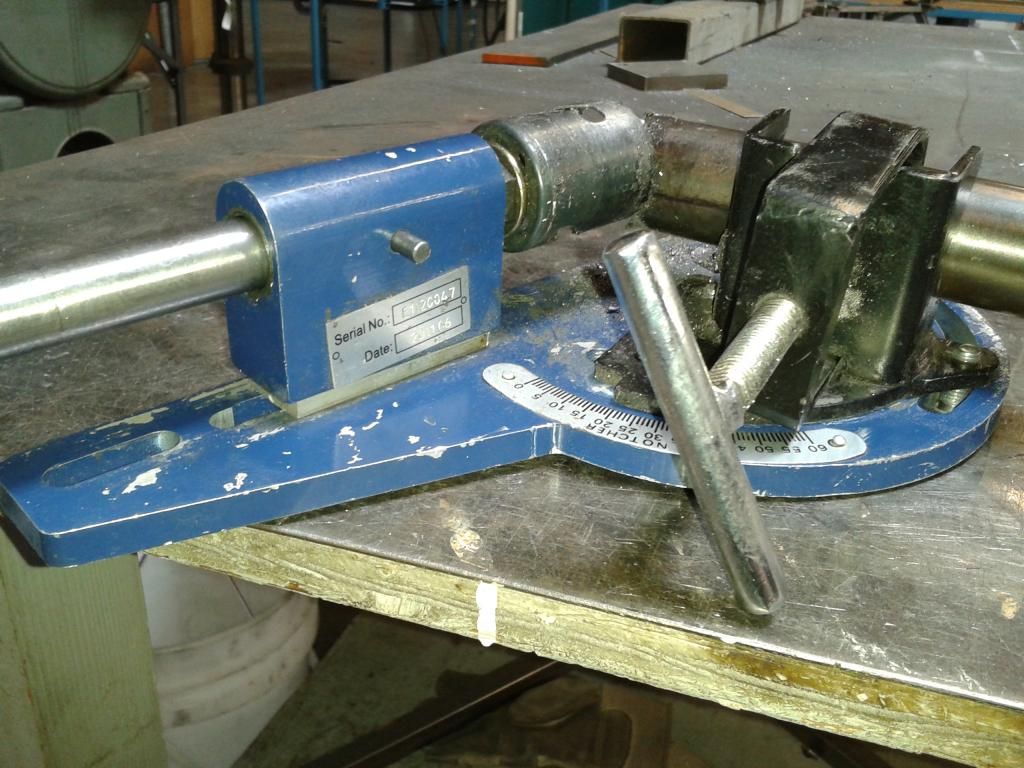
I used a spacer and longer bolts to allow me to do the offset notching on the tube:
Of course, after carefully notching one side, then carefully measuring the other side (keep in mind, the length of this tube varies dramatically with its height since it is dropping between angled bars), I was horrified to discover this gap:
And of course it was the last piece of tubing I had in that size! I really hate ordering only one piece of tubing, with the associated shipping charges!
As I waited for my replacement tube to arrive, I notched and fitted the rear vertical bars that tied in some of the rear suspension, and would be the anchor point for the double frame rails:
Fortunately I remembered a lesson from earlier in the build, when working with weird compound angles like this: I used my properly-notched but too short piece of tubing to make a card stock template. If I would have planned better I would have used a short scrap of tubing to rough in the notch, but hindsight is 20/20!
After marking and notching the new tube I was able to get a nice snug fit:
I had precisely positioned the height of that tube with shims, after adjusting it (and leveling the steering rack mounts) when adjusting for bump steer (detailed in the last entry). I went ahead and fully welded this tube in place:
Next up was positioning the rack mounts. Rather than just making them perfectly level, I had a sudden epiphany that I could precisely adjust the height of the rack at this point, perhaps getting even less bump steer in the process. I bolted back on my bump steer checking apparatus, and used some threaded rod to make very fine adjustments:
I also marked the extremes of the rack steering travel so I could line everything up with the rack perfectly centered in the chassis:

With those adjustments done I was able to get the total bump steer below 0.01" per side through the entire suspension travel!
Next up I tacked then finish welded the rack mounts in place:

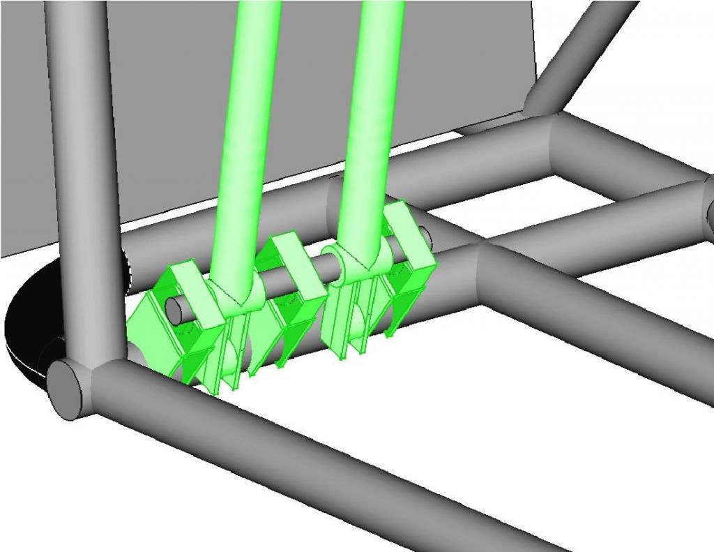
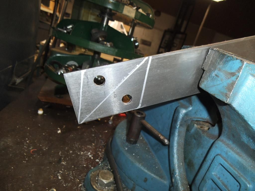
Next project was to fabricate some tabs that would serve the dual purpose of gusseting the top strut mounts, and providing the top mount for the front suspension travel limiters.
I mocked the pieces up in cardboard first, using long threaded rod to make sure they were perfectly aligned with the point on the lower control arm where the limiter cable would eventually attach.
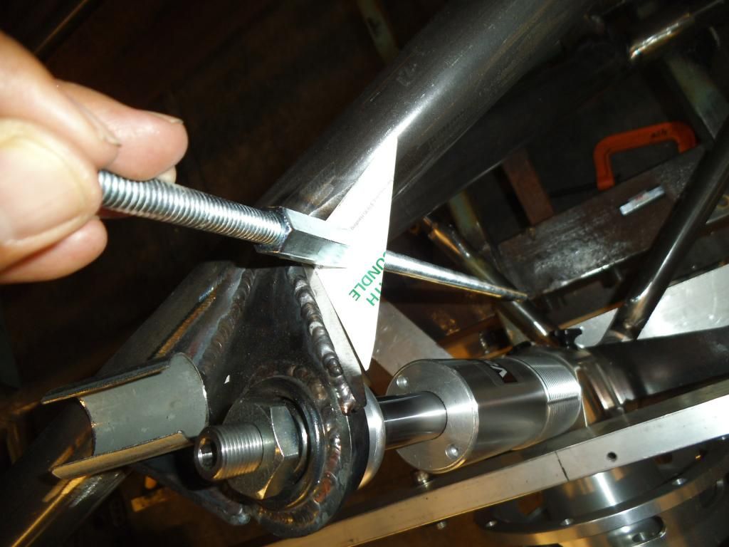
I used the cardboard to mark and cut out the metal pieces:
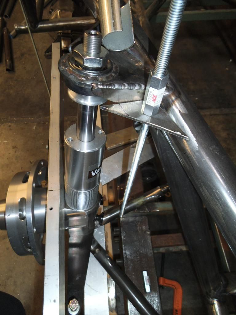
Next up was the initial fitting and tacking of the metal piece, where I discovered that the cardboard flexed just a bit more, requiring some additional cutting on the metal:
Next up will be wrapping up these mounts, then moving on to the double frame rails.
Sorry for the lack of updates, too many things going on between work and other racing, but finally getting more time on the race truck.
First off, a belated "Thank You" to all who attended the Pacific Coast Diesel Nationals Presented by ISSPRO! While we had scorching heat in prior years, this time we had torrential downpours, but somehow squeezed in the racing and sled pulling between rainstorms. We still had a huge crowd of spectators who braved the rain to cheer on the competitors.
A few details on the other items:
My Vega, which has always hooked really well (once I had the suspension all dialed in) suddenly started spinning the tires badly, and it turned out to be the original Koni shocks finally getting worn out. I picked up a set of QA1 double adjustable shocks and got it working well again. Just as I was fine-tuning the new shocks, it suddenly started spinning again. I was able to fine tune it and pick some ET back up, only to discover the slicks were down to the cords! I guess the suspension is REALLY working well to be able to hook up with cords showing!
My next fiasco was at a race with a really bad crosswind at the top end of the track, it ripped the scoop off on one pass, and blew the driver's window out on another! Weird crap to be happening at 147+ mph! A couple other cars had their side windows blown out too, including one with original glass that made a huge mess on the track.
I ended up trading some parts for a complete Vega hood with scoop, and made a new side window.
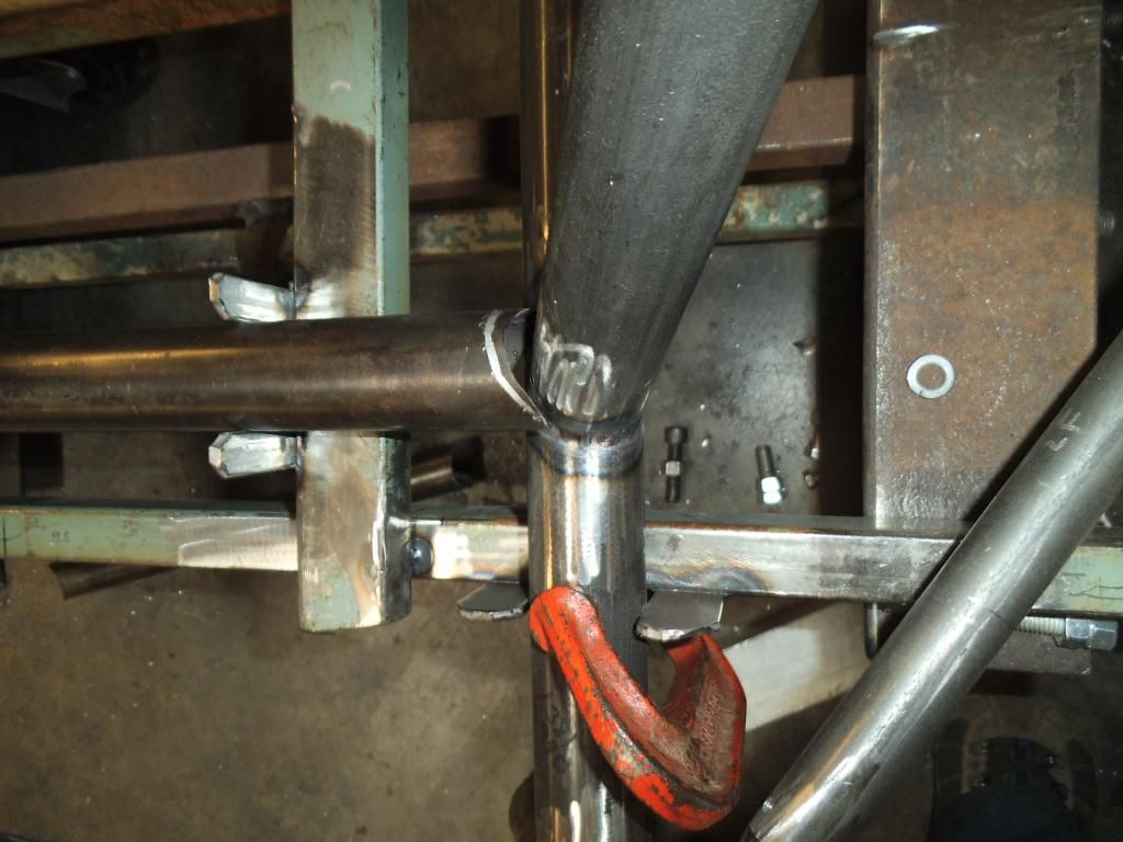
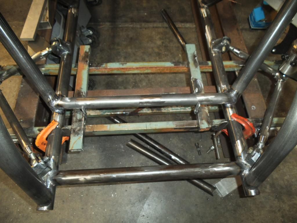
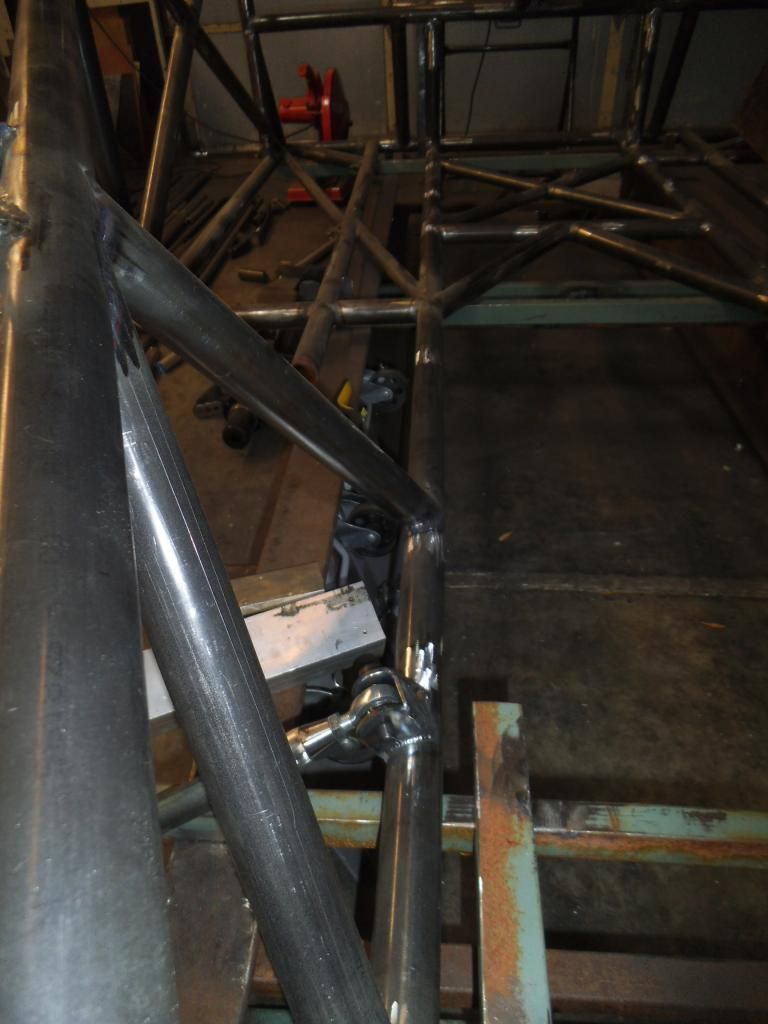
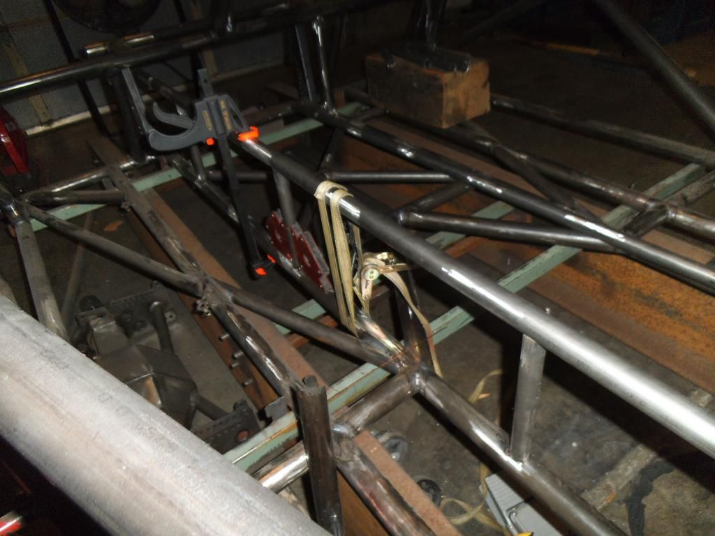
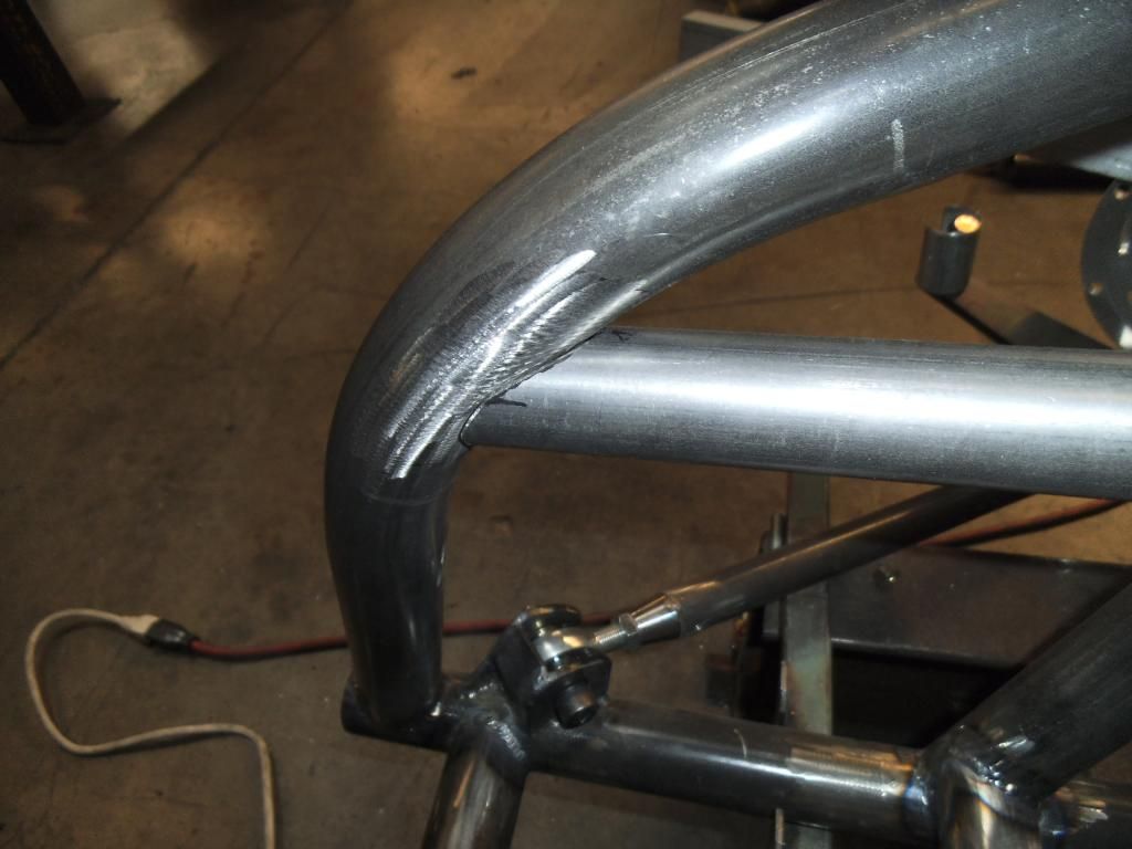
Back to the race truck, I started working on the steering mount crossmember, which was positioned at a weird compound angle (and offset from center) of the diagonal strut support bars.
I used a spacer and longer bolts to allow me to do the offset notching on the tube:
Of course, after carefully notching one side, then carefully measuring the other side (keep in mind, the length of this tube varies dramatically with its height since it is dropping between angled bars), I was horrified to discover this gap:
And of course it was the last piece of tubing I had in that size! I really hate ordering only one piece of tubing, with the associated shipping charges!
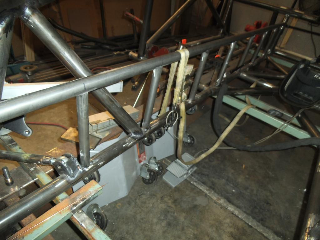
As I waited for my replacement tube to arrive, I notched and fitted the rear vertical bars that tied in some of the rear suspension, and would be the anchor point for the double frame rails:
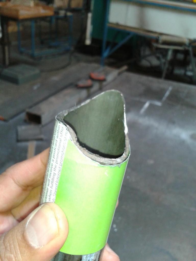
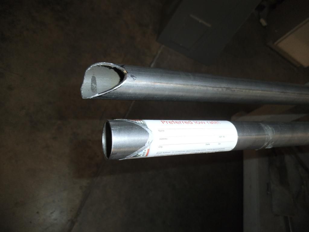
Fortunately I remembered a lesson from earlier in the build, when working with weird compound angles like this: I used my properly-notched but too short piece of tubing to make a card stock template. If I would have planned better I would have used a short scrap of tubing to rough in the notch, but hindsight is 20/20!
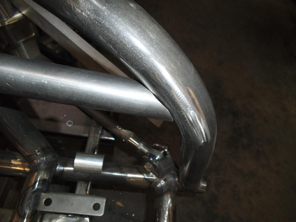
After marking and notching the new tube I was able to get a nice snug fit:
I had precisely positioned the height of that tube with shims, after adjusting it (and leveling the steering rack mounts) when adjusting for bump steer (detailed in the last entry). I went ahead and fully welded this tube in place:
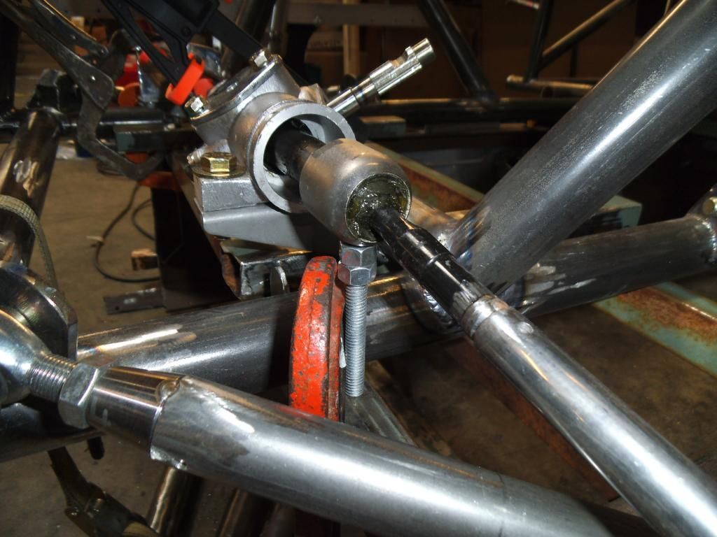
Next up was positioning the rack mounts. Rather than just making them perfectly level, I had a sudden epiphany that I could precisely adjust the height of the rack at this point, perhaps getting even less bump steer in the process. I bolted back on my bump steer checking apparatus, and used some threaded rod to make very fine adjustments:
I also marked the extremes of the rack steering travel so I could line everything up with the rack perfectly centered in the chassis:
With those adjustments done I was able to get the total bump steer below 0.01" per side through the entire suspension travel!
Next up I tacked then finish welded the rack mounts in place:
Next project was to fabricate some tabs that would serve the dual purpose of gusseting the top strut mounts, and providing the top mount for the front suspension travel limiters.
I mocked the pieces up in cardboard first, using long threaded rod to make sure they were perfectly aligned with the point on the lower control arm where the limiter cable would eventually attach.
I used the cardboard to mark and cut out the metal pieces:
Next up was the initial fitting and tacking of the metal piece, where I discovered that the cardboard flexed just a bit more, requiring some additional cutting on the metal:
Next up will be wrapping up these mounts, then moving on to the double frame rails.
quito195
New member
- Joined
- Jul 5, 2007
- Messages
- 47
As I recall you live somewhere in Portland. Team tube and metal supermarkets both over off airport way usually stock some DOM/Chromoly items. Saves you the heart ache of shipping and handling as well as the wait. Metal Supermarket will even cut pieces and only charge you for that length. Dig the truck, and am really looking forward to some more updates.
Michael
Comp Diesel Sponsor
- Joined
- Apr 25, 2006
- Messages
- 3,411
As I recall you live somewhere in Portland. Team tube and metal supermarkets both over off airport way usually stock some DOM/Chromoly items. Saves you the heart ache of shipping and handling as well as the wait. Metal Supermarket will even cut pieces and only charge you for that length. Dig the truck, and am really looking forward to some more updates.
Thanks! I am in the Portland area, had not heard of either of those places! I bought most of my tubing from Tube Specialties (local) and the rest mail order from Aircraft Spruce. TS has good prices on 1-5/8" but is more expensive on all the other sizes, plus they have a minimum purchase. I'll check with Team Tube & Metal Supermarket next time I need some! In fact, I need some additional 1" x 0.058" for my firewall structure, will check on getting it there!
Nice update Michael. Making it to the season opener?!?!
Probably won't have the race truck done by then, but I'll keep pushing for it!
Michael
Comp Diesel Sponsor
- Joined
- Apr 25, 2006
- Messages
- 3,411
Yikes, I just checked the prices for 1" x 0.058", Team Tube was $5.56/ft (but have to buy in 24' increments), Metal Supermarket was $8.75/ft. Tube Specialties was $4.90/ft last time I checked, and Aircraft Spruce is $3.70/ft (but was $2.80 last time I bought).
joefarmer
MR. Supreme Overlord
- Joined
- Jul 31, 2006
- Messages
- 6,137
Wow. I need to get a 1" die for my bender. Have a couple little projects that could use 1", but now I'm scared of the cost. LOLYikes, I just checked the prices for 1" x 0.058", Team Tube was $5.56/ft (but have to buy in 24' increments), Metal Supermarket was $8.75/ft. Tube Specialties was $4.90/ft last time I checked, and Aircraft Spruce is $3.70/ft (but was $2.80 last time I bought).
Truck looks good though!
Michael
Comp Diesel Sponsor
- Joined
- Apr 25, 2006
- Messages
- 3,411
Wow. I need to get a 1" die for my bender. Have a couple little projects that could use 1", but now I'm scared of the cost. LOL
Truck looks good though!
LOL, those local places are pretty expensive, but Aircraft Spruce is still pretty reasonable despite their increase!
Michael
Comp Diesel Sponsor
- Joined
- Apr 25, 2006
- Messages
- 3,411
Episode 25:
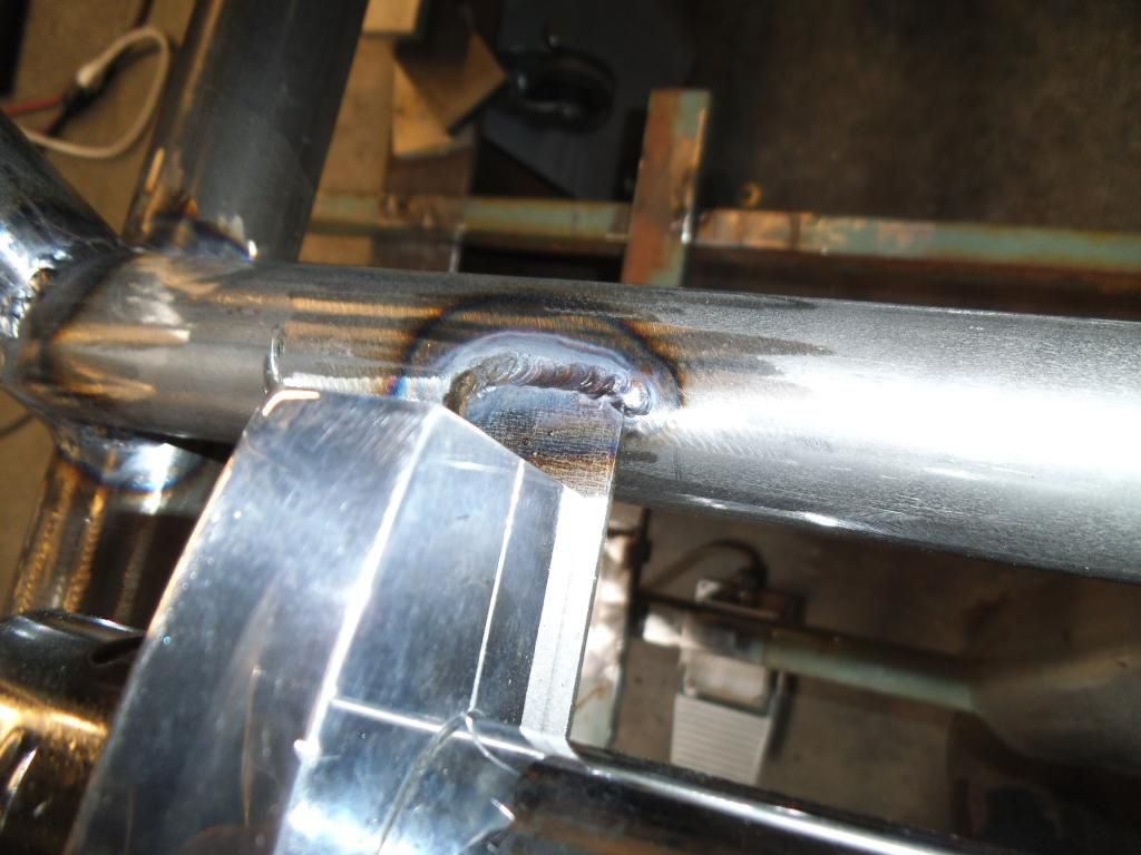
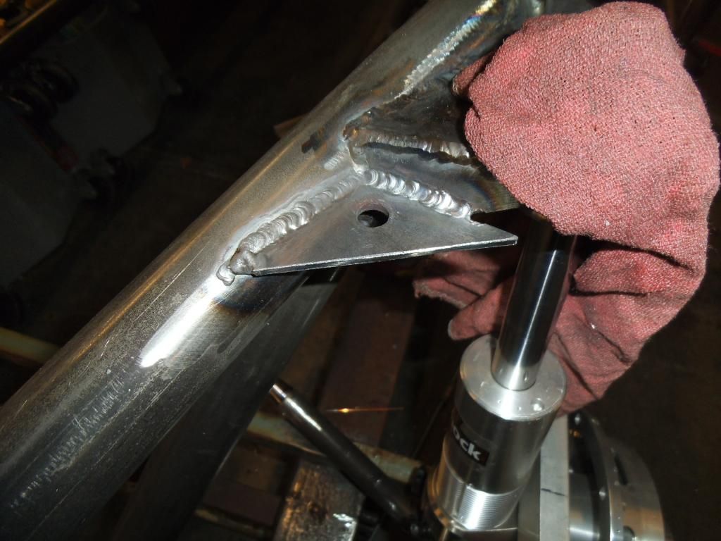
After maneuvering the gusset/mount into a few positions, I figured I would tack it, weld it, then cut off the excess;
On this side I welded it in several short beads (making sure to not overheat the bearing in the nearby strut top mount).
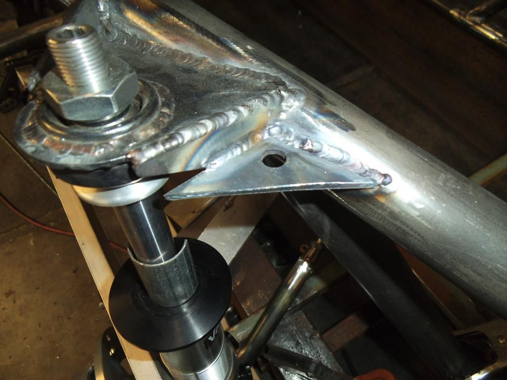
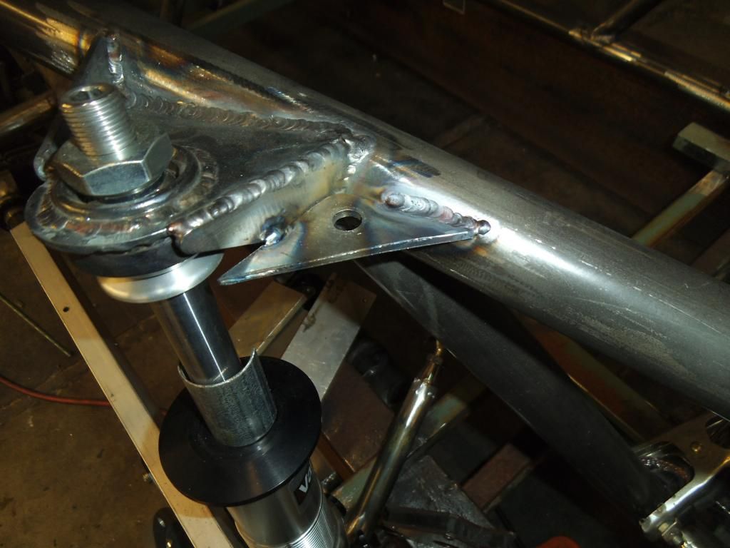
On the other side I was in such a "groove" with a nice bead going, I forgot to take my time to keep from heating up the bearing! I immediately wrapped a wet rag around the bearing to keep it cool.
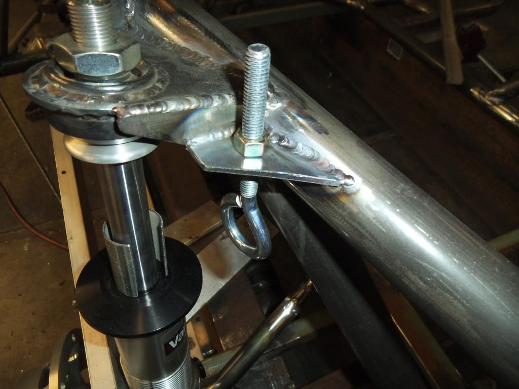
After that it was a simple matter to trim the excess, and test fit the eye bolt:
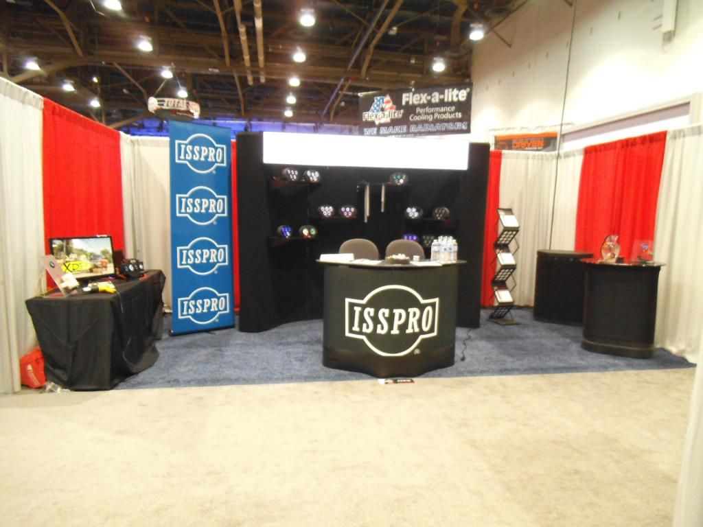
My next big delay in the project was the SEMA trade show, our biggest event of the year. We discovered that all of our table-top gauge displays from prior years had been destroyed in shipping, so it was a mad scramble to make more in our 3D printer and get things set up.
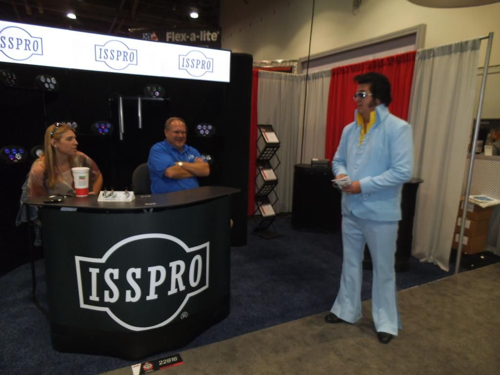
We had a great show, highlighting our new datalogger as well as our new line of waterproof gauges (displayed to the right in a fishbowl complete with live fish).
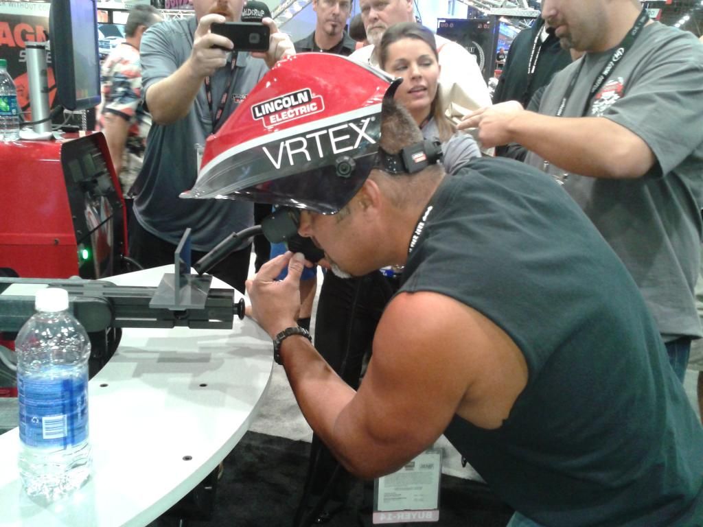
I got to hang out with my old friend Steve Darnell, star of Vegas Rat Rods on the Discovery Channel. We had a fun time playing with the welding simulator at the Lincoln Electric booth.
I also got to spend some time hanging out with my buddy Aaron Hagar, as well as his new business partner Brad Fanshaw (TV host, former BMX racer & executive, and Boyd Coddington protege').
Our booth was so busy all week I swear everyone on the planet must have stopped by. Even Elvis, who seemed more interested in our sales associate Jen than in any gauges...
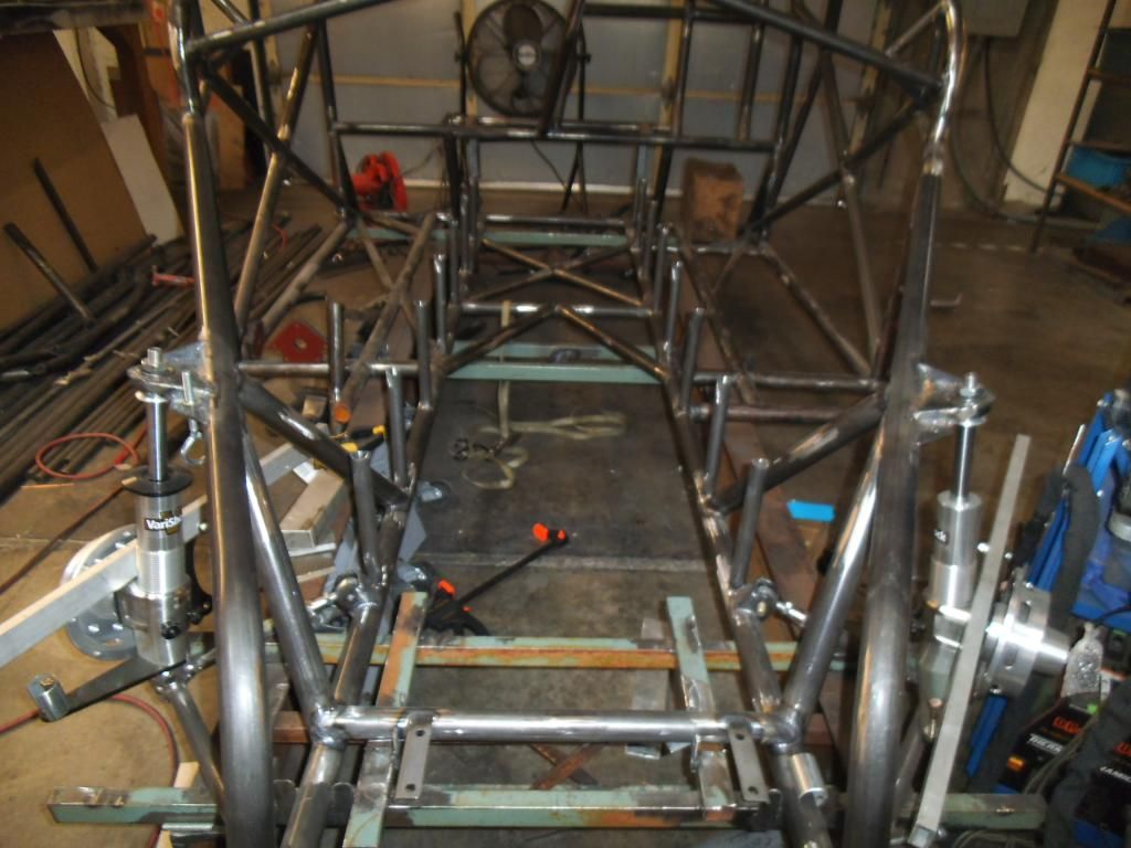
After all of that I finally got back to the race truck and its double frame rails. Double frame rails are seen on higher powered Pro Mod type cars, but with the torque of a diesel they have become necessary even for something running in the 8's or 7's, as several of the original NHRA Pro Stock Truck chassis (which are not double frame rail) have seen issues with the torque of a diesel.
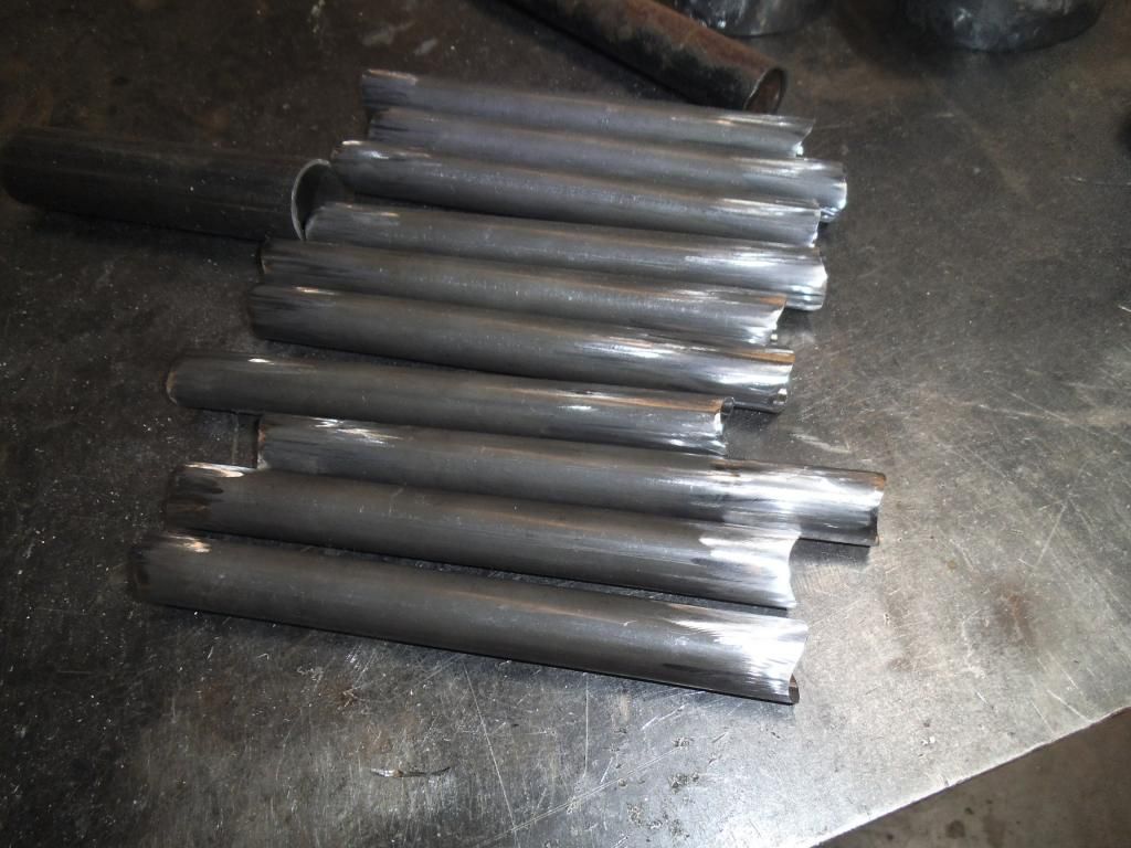
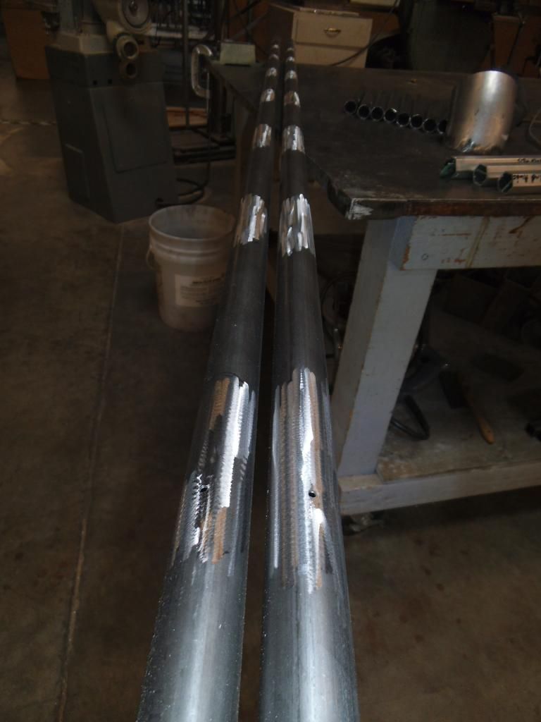
Fortunately the first steps included 10 different tubes cut and notched identically. I could finally feel like I was making progress in more of an asssembly line approach, making 10 identical parts. Sure, I still had to swap hole saws (different sized notches at each end), but I'm sure that is the most cuts I have made with my notcher without adjusting the angle!
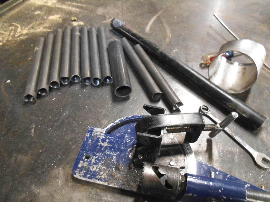
Even the metal prep (removing mill scale from inside and outside the tubing at the ends) was seemingly easier since I was doing so many at once.
I prepped all of the matching spots on the chassis for each of these vertical supports for the double frame rails:
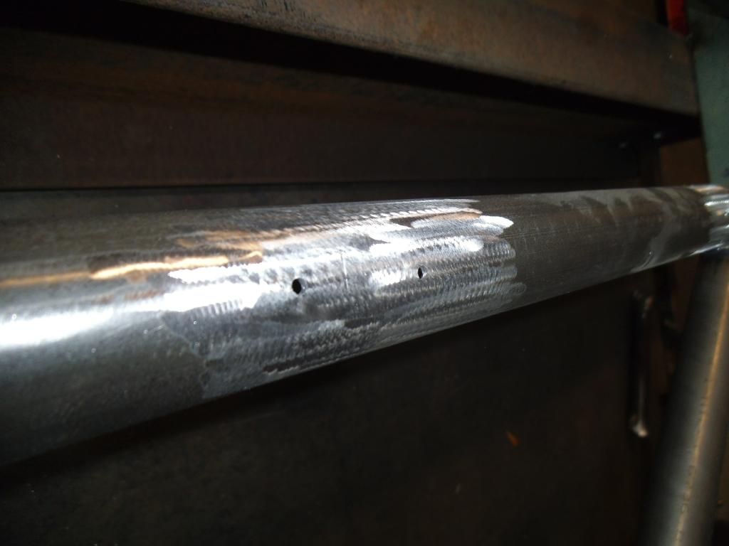
While I was at it I went ahead and drilled the pressur relief holes for both these tubes and the upcoming diagonal tubes. I have a bad habit of forgetting those holes!
I even got carried away with my prep and hole drilling on the top rails of the double rails, as I forgot about the length loss due to notching, so I will probably be re-drilling those holes (and welding these ones shut).
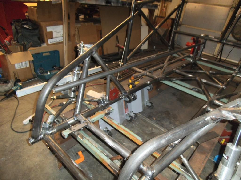
I started with the two end vertical supports, wanting to make sure they were perfectly vertical, then using them as a guide to position the remaining tubes:
The next tubes sometimes needed some "adjustment" in their position after tack welding them in place. This was accomplished by placing a larger diameter tube over it, and applying some good old fashioned brute force:

Hopefully when I am done with all of the vertical supports they will align perfectly with the top tube of the double rails. Then I will get the fun task of carving a weird shaped notch in the end of each of those rails, where it intersects the strut tube right at a bend! Hopefully I have a scrap piece long enough to use for that, so I can use my trick of carving it to fit then making a cardboard template!
After maneuvering the gusset/mount into a few positions, I figured I would tack it, weld it, then cut off the excess;
On this side I welded it in several short beads (making sure to not overheat the bearing in the nearby strut top mount).
On the other side I was in such a "groove" with a nice bead going, I forgot to take my time to keep from heating up the bearing! I immediately wrapped a wet rag around the bearing to keep it cool.
After that it was a simple matter to trim the excess, and test fit the eye bolt:
My next big delay in the project was the SEMA trade show, our biggest event of the year. We discovered that all of our table-top gauge displays from prior years had been destroyed in shipping, so it was a mad scramble to make more in our 3D printer and get things set up.
We had a great show, highlighting our new datalogger as well as our new line of waterproof gauges (displayed to the right in a fishbowl complete with live fish).
I got to hang out with my old friend Steve Darnell, star of Vegas Rat Rods on the Discovery Channel. We had a fun time playing with the welding simulator at the Lincoln Electric booth.
I also got to spend some time hanging out with my buddy Aaron Hagar, as well as his new business partner Brad Fanshaw (TV host, former BMX racer & executive, and Boyd Coddington protege').
Our booth was so busy all week I swear everyone on the planet must have stopped by. Even Elvis, who seemed more interested in our sales associate Jen than in any gauges...
After all of that I finally got back to the race truck and its double frame rails. Double frame rails are seen on higher powered Pro Mod type cars, but with the torque of a diesel they have become necessary even for something running in the 8's or 7's, as several of the original NHRA Pro Stock Truck chassis (which are not double frame rail) have seen issues with the torque of a diesel.
Fortunately the first steps included 10 different tubes cut and notched identically. I could finally feel like I was making progress in more of an asssembly line approach, making 10 identical parts. Sure, I still had to swap hole saws (different sized notches at each end), but I'm sure that is the most cuts I have made with my notcher without adjusting the angle!
Even the metal prep (removing mill scale from inside and outside the tubing at the ends) was seemingly easier since I was doing so many at once.
I prepped all of the matching spots on the chassis for each of these vertical supports for the double frame rails:
While I was at it I went ahead and drilled the pressur relief holes for both these tubes and the upcoming diagonal tubes. I have a bad habit of forgetting those holes!
I even got carried away with my prep and hole drilling on the top rails of the double rails, as I forgot about the length loss due to notching, so I will probably be re-drilling those holes (and welding these ones shut).
I started with the two end vertical supports, wanting to make sure they were perfectly vertical, then using them as a guide to position the remaining tubes:
The next tubes sometimes needed some "adjustment" in their position after tack welding them in place. This was accomplished by placing a larger diameter tube over it, and applying some good old fashioned brute force:
Hopefully when I am done with all of the vertical supports they will align perfectly with the top tube of the double rails. Then I will get the fun task of carving a weird shaped notch in the end of each of those rails, where it intersects the strut tube right at a bend! Hopefully I have a scrap piece long enough to use for that, so I can use my trick of carving it to fit then making a cardboard template!
quito195
New member
- Joined
- Jul 5, 2007
- Messages
- 47
Yikes, I just checked the prices for 1" x 0.058", Team Tube was $5.56/ft (but have to buy in 24' increments), Metal Supermarket was $8.75/ft. Tube Specialties was $4.90/ft last time I checked, and Aircraft Spruce is $3.70/ft (but was $2.80 last time I bought).
Good lord that's through the roof. I haven't ever bought from either without an account but that's still atrociously high. Well maybe someday in case of an emergency. As always keep up the good work.
Michael
Comp Diesel Sponsor
- Joined
- Apr 25, 2006
- Messages
- 3,411
Episode 26:
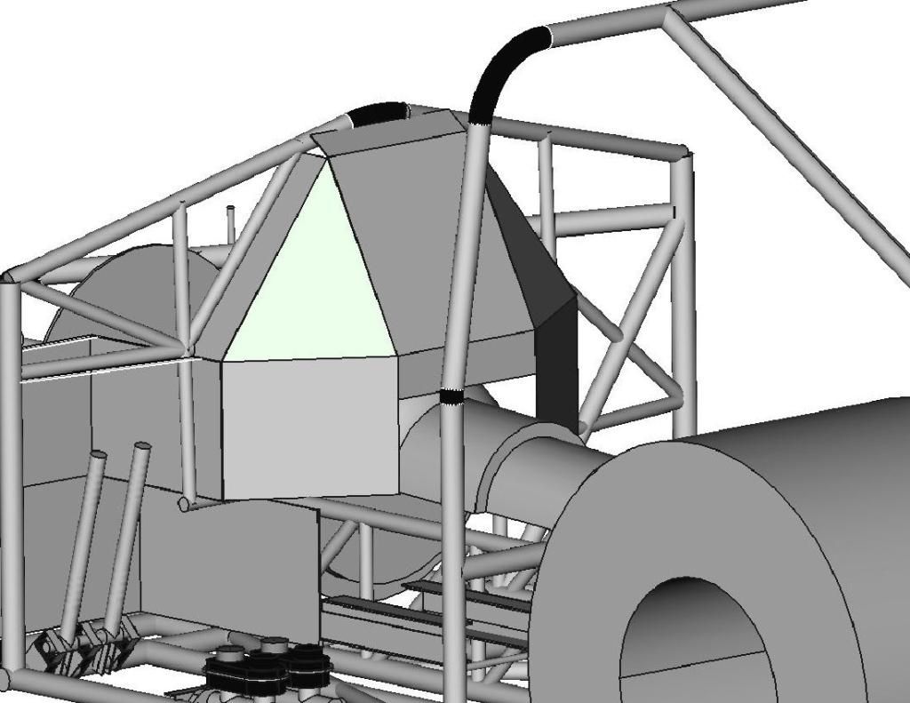
I was nearing the time to order more 1" tubing to form the structure of the firewall, so I got back on the CAD system to figure out how the plates of the firewall would be positioned, so I could order that material at the same time and save on shipping.
With the amount of engine setback (necessary for good weight distribution with the heavy diesel engine), I would have the plane of the flexplate/flywheel at my shins, and my feet would be next to the rear portion of the oil pan (where connecting rods occasionally peek out like a metal groundhog on steroids). To keep from gaining the nickname 'Stumpy" I want the vertical portions of the "footbox" section to be 0.125" 4130 plate. The horizontal and angled portions will be 0.080" thick 4130, still much more protection than the required 0.024" mild steel.
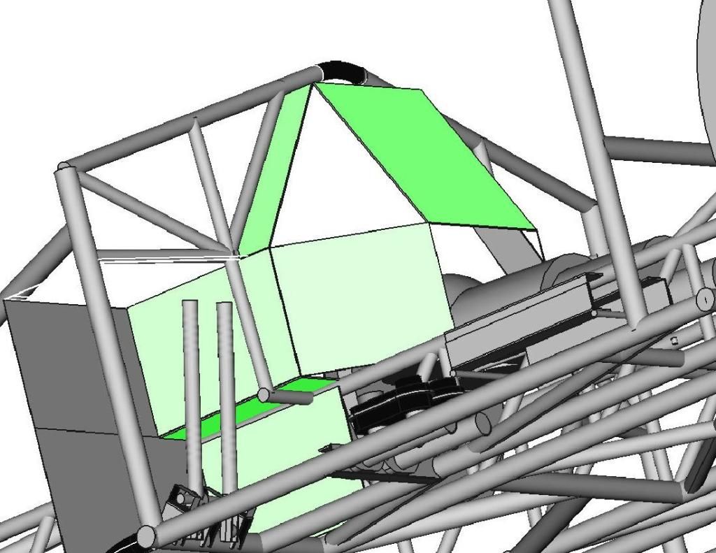
The top area of that center section will be protecting me from shrapnel in the event of a high pressure turbo failure, so that part is important too!
While I have been happy with the freeware 3D CAD program (FreeCAD 13), it does have a few shortcomings and bugs in it. It is very easy to create rectangular and cylindrical shaped solids, but to get the triangular shape to fill in the opening in the above picture, I needed to cut two sections from a rectangle. Once I tried to rotate the part in space it would screw up the cuts. I finally figured out that it could rotate the part if it was part of an assembly or "union" but not by itself, so I created a little speck of dust (0.01 mm cube) that I "assembled" as a union with my desired triangle, then it allowed me to rotate it into position. I had to repeat the "union" process to rotate it about another axis, but it all worked out.
Now that I had all of the plate sections worked out, I needed to figure out how to best fit those shapes into a single plate of material, so I could minimize the material and shipping costs. I switched over to the 2D CAD program and played around with the shapes like a giant puzzle, moving them around until I had the least amount of wasted material.
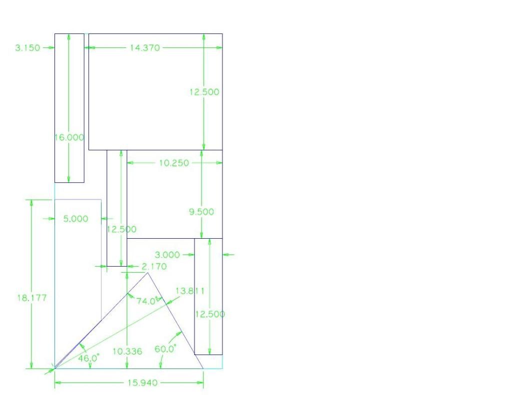
I plan to use my plasma cutter for the necessary "jagged" cuts, but then use a big metal shear to make the straight cuts.
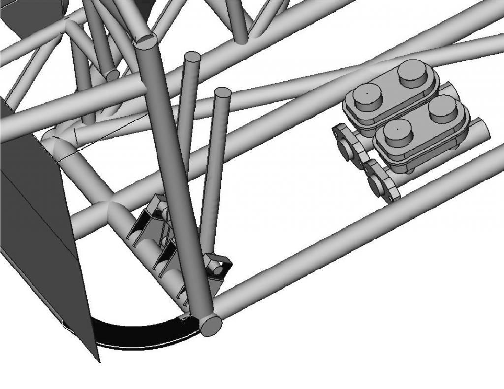
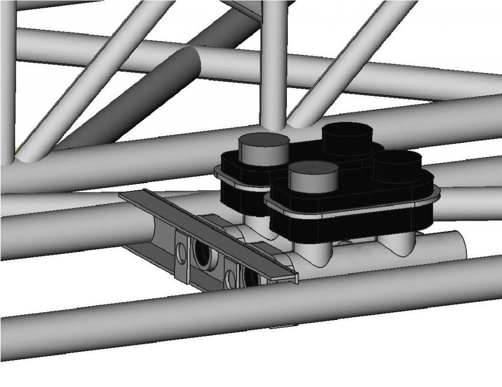
While I was doing all this CAD work I decided to go back to the seat mount design I was working on before. I had previously designed mounts for the master cylinders and brake pedals, and had placed the master cylinders as far back as possible, figuring I would want more of an open floor in front of the seat.
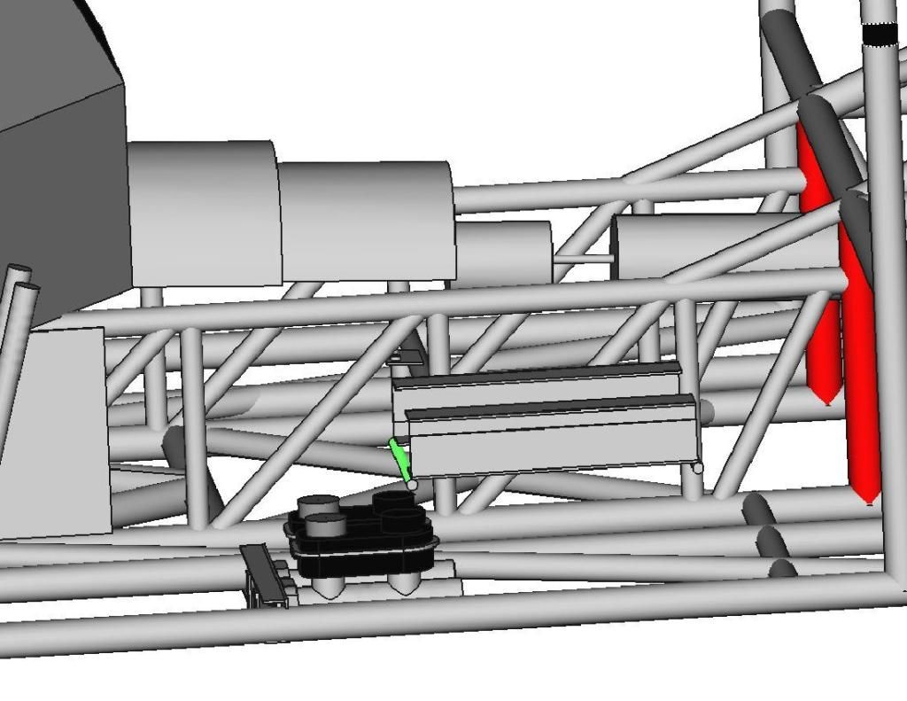
Unfortunately this placed the seat mounts directly over the master cylinder rear caps, and compromised the geometry of the mounts. It was a lot easier to move these in CAD than it would have been after welding! I just moved the whole assembly forward 50mm and gained the clearance I needed.
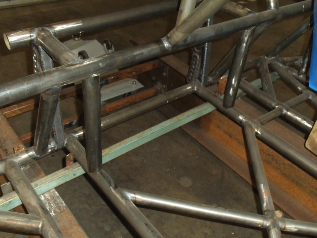
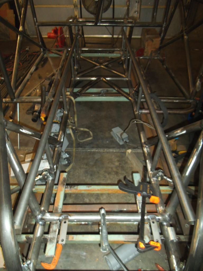
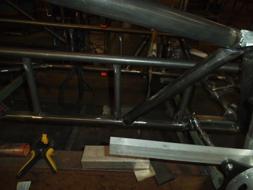
Continuing on the double rails, once I got to the intermediate vertical tubes I used a ratchet strap and clamp to squeeze the top tube down, hopefully holding everything in alignment.
I tried experimenting with that approach versus a "freehand" approach using the digital angle finder like I did the end ones, it was almost a toss up between the time spent setting up the clamps and tube versus taking a little more care with the angle finder and quickly moving from one side to the other on my tack welds (so the weld draw on each side could pull against each other).
I ran all of the truly vertical double frame rail supports (5 of them) on one side, then did the mirror image on the other side.
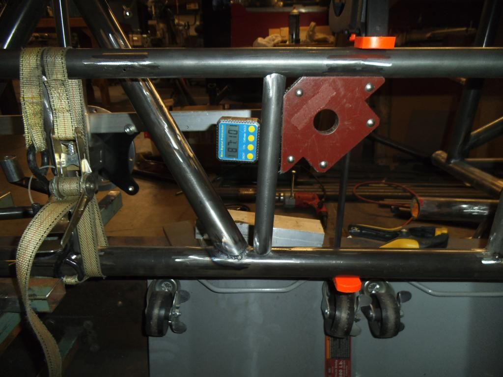
The "vertical" supports that coincide with the engine mount front plate and the mid plate will both be slanted back 2.9° from vertical, to match the slope of the engine/trans (so I have full engagement with these tubes when I weld brackets on at that 2.9° angle). Since the digital protractor was referencing horizontal instead of vertical, the 2.9° angle shows up as 87.1°. And you thought you would never use geometry again after school...
All of those vertical braces were much easier to insert into place with the top rails not welded in yet (as they would require separation of the bottom and top rails to "pop" into place). In this photo you can see the 2.9° tubes, where the front plate of the engine mount will eventually go.
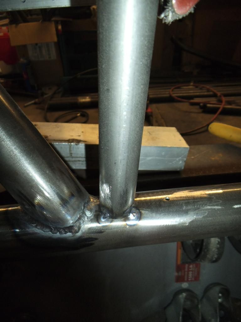
On all of these tubes I was tacking in four opposite spots, to keep the tubes securely positioned. Due to weld draw, I will wait until the whole assembly is tacked together before finish welding it.
Before I got too far I decided to verify that I had the planned clearance between the seat and the double frame rails. While it is nice to lay this stuff out in CAD, I always feel better when I can see the clearance in the real world!
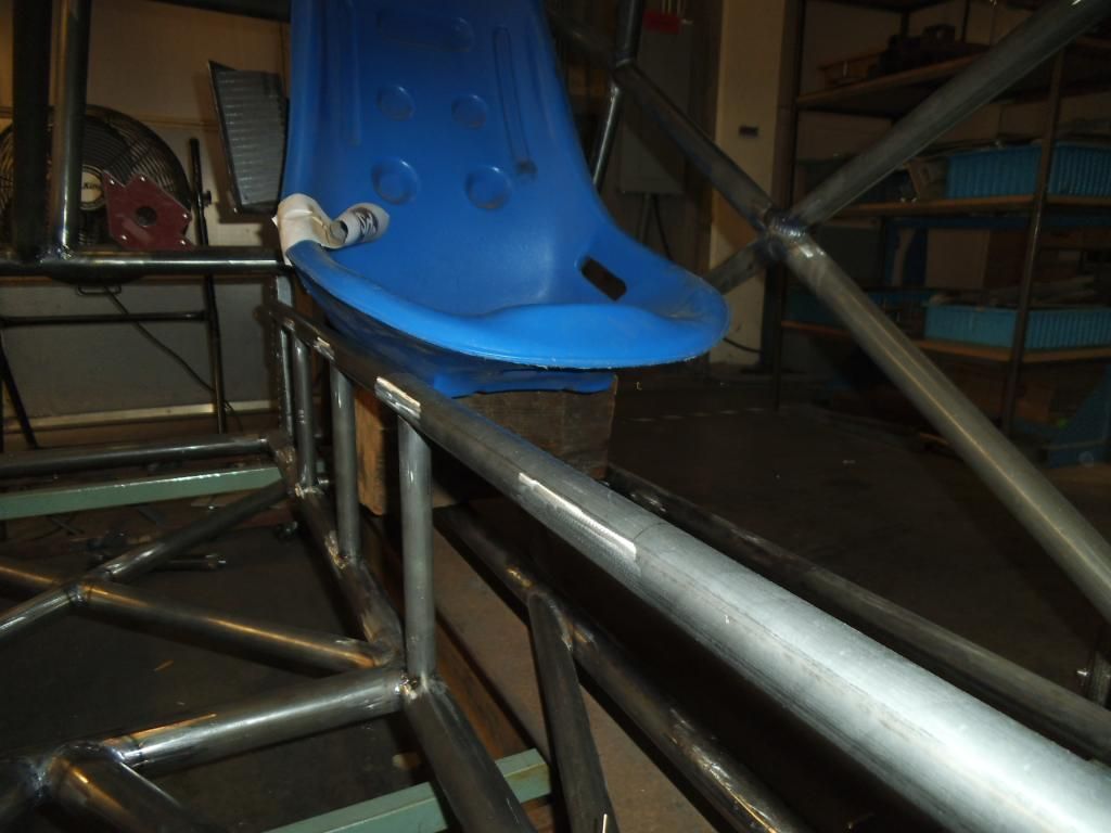
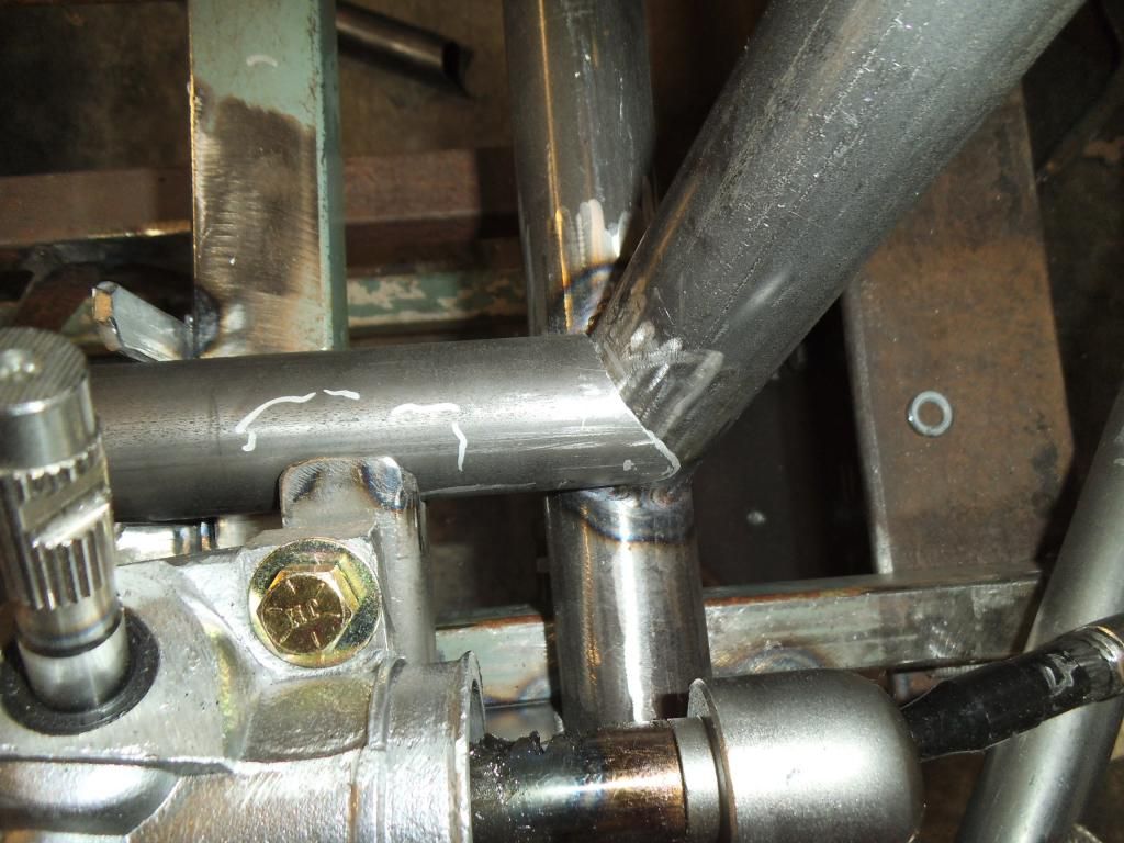
The front edge of the top double frame rails shows the weird compound angle I will have to notch next. Not looking forward to that one!
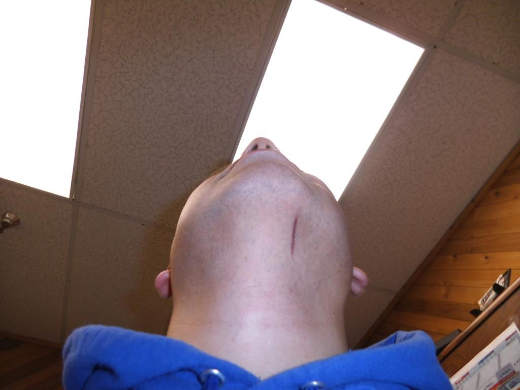
Of course when things seem to be going well, something weird has to go wrong! This was a weird freak occurrence but something you have to be careful about when working around hot items and a roll cage! I had just finished a weld in an awkward position, went to climb out of the cage and smacked my head & welding hood on the top of the cage, which swung the hood down over my face just as the still-red-hot filler rod caught one of the double frame rail tubes, flipping its hot end right into my chin and under the hood (making it VERY hard to get out). I could hear the flesh searing as I tried to grab the damn thing, and it scooted along a nice straight line as I tried to extricate it!
Next up is the last pair of frame rail uprights, then the aforementioned nightmare notching of the top tubes, tacking them in place, then the 45° diagonals for the double rails. After that it will be on to the tubing forming the firewall, before I move the whole chassis forward on the jig to continue on the rear tubes.
I was nearing the time to order more 1" tubing to form the structure of the firewall, so I got back on the CAD system to figure out how the plates of the firewall would be positioned, so I could order that material at the same time and save on shipping.
With the amount of engine setback (necessary for good weight distribution with the heavy diesel engine), I would have the plane of the flexplate/flywheel at my shins, and my feet would be next to the rear portion of the oil pan (where connecting rods occasionally peek out like a metal groundhog on steroids). To keep from gaining the nickname 'Stumpy" I want the vertical portions of the "footbox" section to be 0.125" 4130 plate. The horizontal and angled portions will be 0.080" thick 4130, still much more protection than the required 0.024" mild steel.
The top area of that center section will be protecting me from shrapnel in the event of a high pressure turbo failure, so that part is important too!
While I have been happy with the freeware 3D CAD program (FreeCAD 13), it does have a few shortcomings and bugs in it. It is very easy to create rectangular and cylindrical shaped solids, but to get the triangular shape to fill in the opening in the above picture, I needed to cut two sections from a rectangle. Once I tried to rotate the part in space it would screw up the cuts. I finally figured out that it could rotate the part if it was part of an assembly or "union" but not by itself, so I created a little speck of dust (0.01 mm cube) that I "assembled" as a union with my desired triangle, then it allowed me to rotate it into position. I had to repeat the "union" process to rotate it about another axis, but it all worked out.
Now that I had all of the plate sections worked out, I needed to figure out how to best fit those shapes into a single plate of material, so I could minimize the material and shipping costs. I switched over to the 2D CAD program and played around with the shapes like a giant puzzle, moving them around until I had the least amount of wasted material.
I plan to use my plasma cutter for the necessary "jagged" cuts, but then use a big metal shear to make the straight cuts.
While I was doing all this CAD work I decided to go back to the seat mount design I was working on before. I had previously designed mounts for the master cylinders and brake pedals, and had placed the master cylinders as far back as possible, figuring I would want more of an open floor in front of the seat.
Unfortunately this placed the seat mounts directly over the master cylinder rear caps, and compromised the geometry of the mounts. It was a lot easier to move these in CAD than it would have been after welding! I just moved the whole assembly forward 50mm and gained the clearance I needed.
Continuing on the double rails, once I got to the intermediate vertical tubes I used a ratchet strap and clamp to squeeze the top tube down, hopefully holding everything in alignment.
I tried experimenting with that approach versus a "freehand" approach using the digital angle finder like I did the end ones, it was almost a toss up between the time spent setting up the clamps and tube versus taking a little more care with the angle finder and quickly moving from one side to the other on my tack welds (so the weld draw on each side could pull against each other).
I ran all of the truly vertical double frame rail supports (5 of them) on one side, then did the mirror image on the other side.
The "vertical" supports that coincide with the engine mount front plate and the mid plate will both be slanted back 2.9° from vertical, to match the slope of the engine/trans (so I have full engagement with these tubes when I weld brackets on at that 2.9° angle). Since the digital protractor was referencing horizontal instead of vertical, the 2.9° angle shows up as 87.1°. And you thought you would never use geometry again after school...
All of those vertical braces were much easier to insert into place with the top rails not welded in yet (as they would require separation of the bottom and top rails to "pop" into place). In this photo you can see the 2.9° tubes, where the front plate of the engine mount will eventually go.
On all of these tubes I was tacking in four opposite spots, to keep the tubes securely positioned. Due to weld draw, I will wait until the whole assembly is tacked together before finish welding it.
Before I got too far I decided to verify that I had the planned clearance between the seat and the double frame rails. While it is nice to lay this stuff out in CAD, I always feel better when I can see the clearance in the real world!
The front edge of the top double frame rails shows the weird compound angle I will have to notch next. Not looking forward to that one!
Of course when things seem to be going well, something weird has to go wrong! This was a weird freak occurrence but something you have to be careful about when working around hot items and a roll cage! I had just finished a weld in an awkward position, went to climb out of the cage and smacked my head & welding hood on the top of the cage, which swung the hood down over my face just as the still-red-hot filler rod caught one of the double frame rail tubes, flipping its hot end right into my chin and under the hood (making it VERY hard to get out). I could hear the flesh searing as I tried to grab the damn thing, and it scooted along a nice straight line as I tried to extricate it!
Next up is the last pair of frame rail uprights, then the aforementioned nightmare notching of the top tubes, tacking them in place, then the 45° diagonals for the double rails. After that it will be on to the tubing forming the firewall, before I move the whole chassis forward on the jig to continue on the rear tubes.
Michael
Comp Diesel Sponsor
- Joined
- Apr 25, 2006
- Messages
- 3,411
Episode 27:
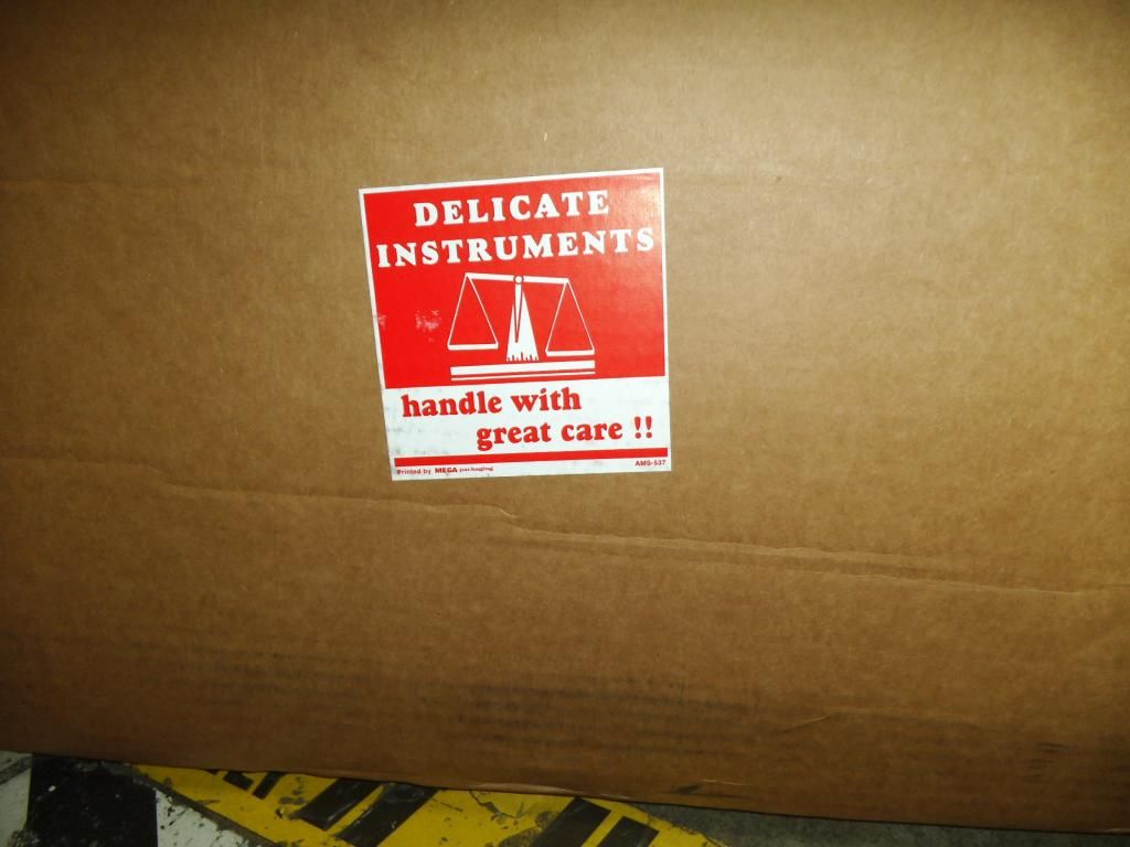
Remember that 4130 chrome moly sheet and plate I was ordering for the firewall last episode? Apparently someone at AircraftSpruce.com's shipping department has a sense of humor. Pretty sure even the worst UPS package manglers would have had a hard time hurting 4130 plate.
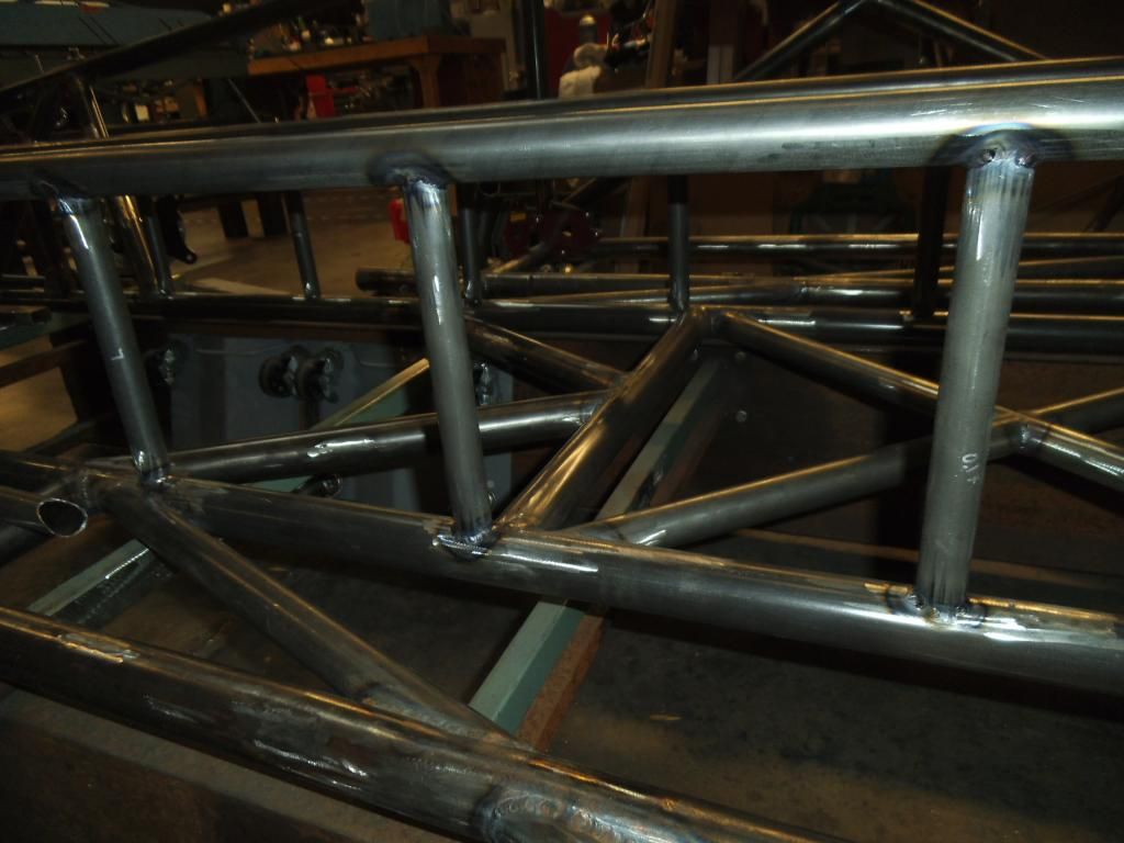
After all the vertical supports were in place I double checked their alignment. They looked like a couple of rows of little telephone poles sticking out there!
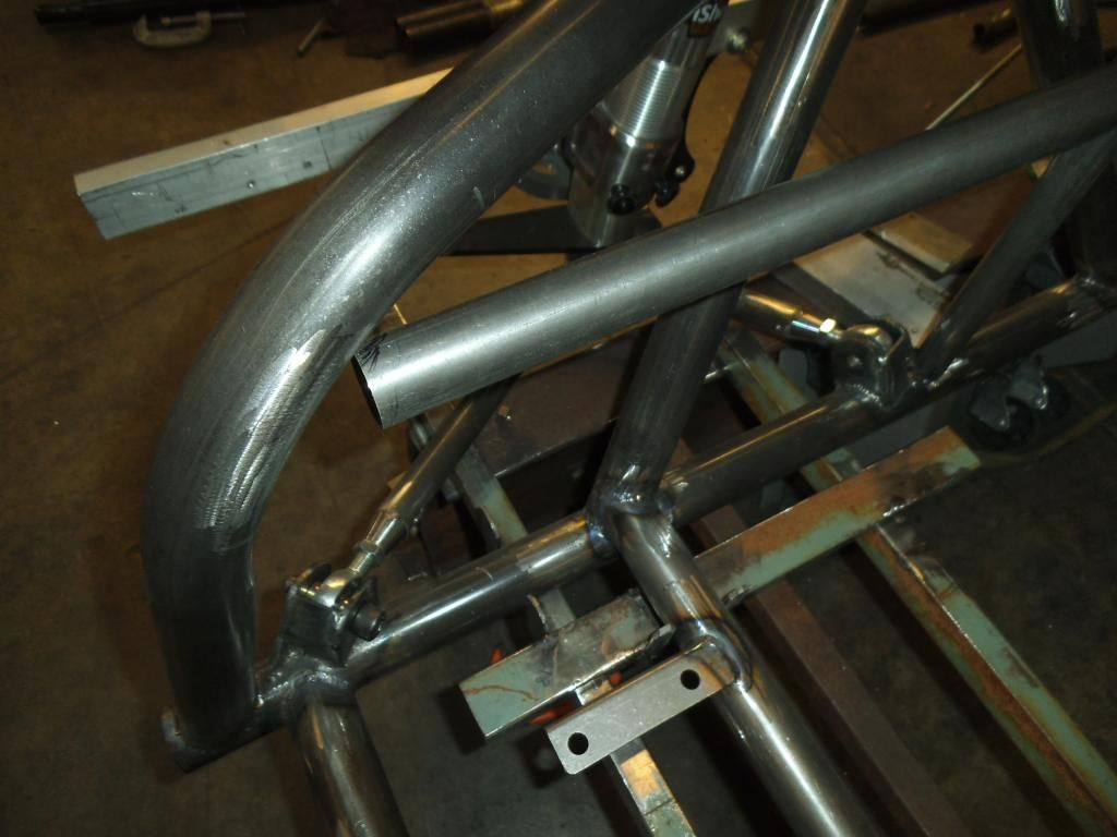
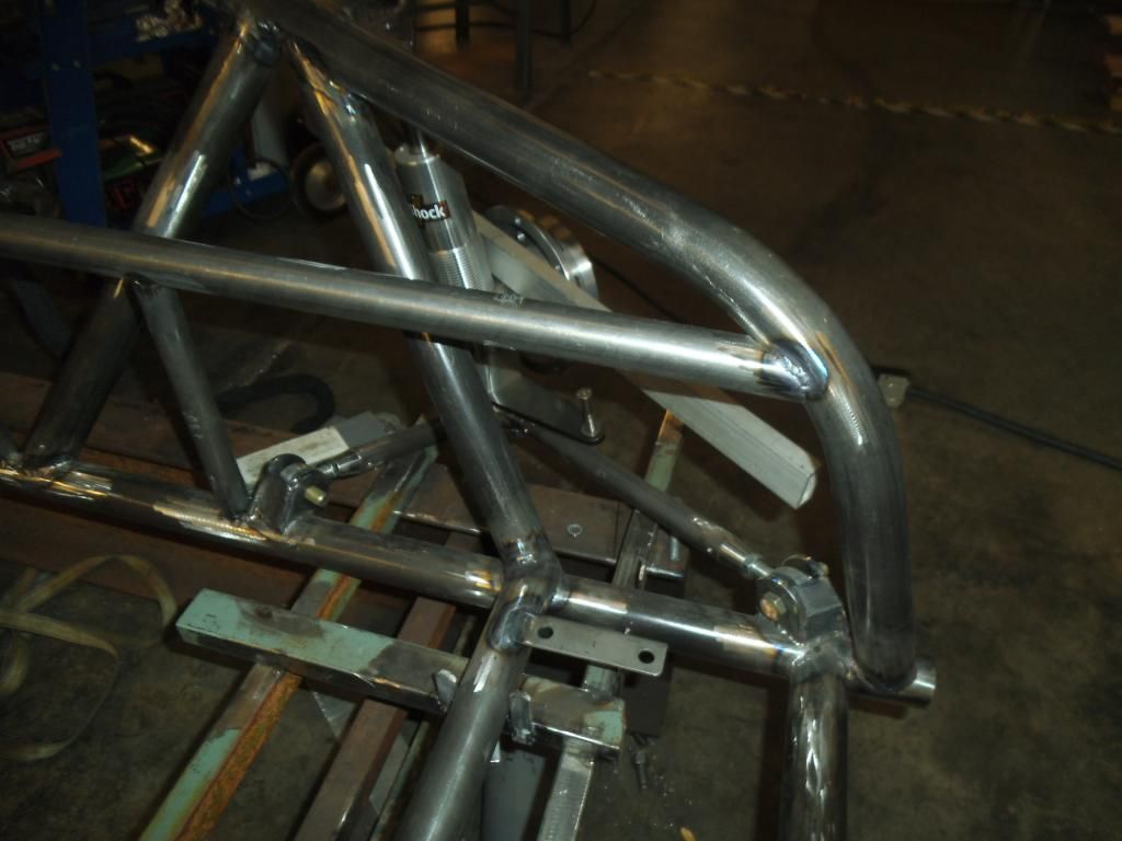
Next up was a task I had been dreading, the notching of the double frame rail tubes where they ran into a weird curve and compound angle. I started with a few rough cuts to get me close:
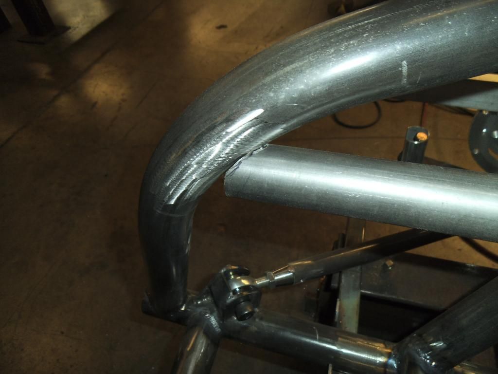
A little more work with an angle grinder and die grinder yielded a nice no-gap interface.
I used a piece of card stock to trace the shape from the first side, then reversed it into a mirror image and marked up the other side's tube for cutting.
Rough cutting to that traced shape got me to a near perfect fit first try!
Next up was to carefully measure then cut and notch the other end of these top tubes, where they intersect with large vertical supports that form a "box" to help transmit the extreme forces of the 4-link brackets into the rest of the chassis.

Once the notching and fitting was done in the rear, it was time to cinch the top tubes down and begin tack welding it at all of its interfaces (10 of them at this point).
Once the tack welds were in place and I had verified that everything was still in alignment, I began finish welding the end connections, going an inch or so at a time (trying to avoid weld draw from too much heating). I also finish welded the areas that would be blocked off by the diagonals which were going in next. I need to avoid painting (or welding) myself into a corner!
I cut and notched the first pair of diagonals. I would have normally used the magnetic corner clamps to hold these tubes in place, but this spot was too small for them! A couple of spring clamps did the job (but being plastic I had to be careful not to melt them)!

As with the other tubes, I initially tacked the diagonals into place.
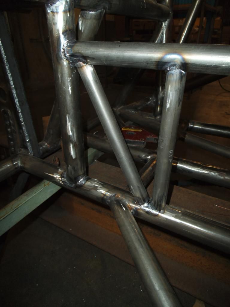
Once they were both tacked in I started finish welding both the diagonals and all the other joints in the double frame rails.

Some of these joints were a little tricky to get to, requiring me to either lie on the floor or on the bars that form the bottom of the chassis.
I struggled with trying to press the foot pedal of the welder up against the jig or chassis, but finally dug out a long strip of velcro to help me keep the pedal tied to my knee while I used the other knee to press the pedal.
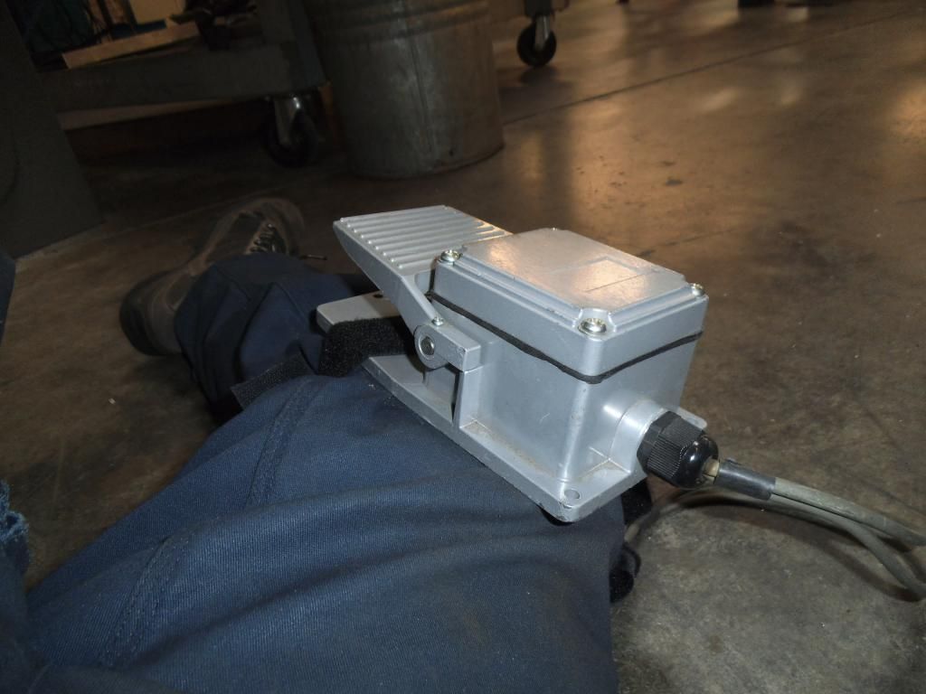
This worked pretty well, but there were a few spots where I was too contorted to even work the pedal that way! At that point I switched over and used the thumb switch on my torch head. While this was easier to do in weird positions, it meant getting my amperage set perfectly on the welder (since I couldn't modulate the amperage like I did with the foot pedal).
Joint by joint, I worked my way welding an inch at a time (usually splitting between two close together welds) until I had done all 40 of the joints.

About halfway through I finally finished burning through my first large argon bottle (after upgrading from the smaller bottles that I had been emptying too often).
Next up: the remaining double frame rail diagonals. I am beginning to see why so few race cars (and trucks) are built with true double frame rails. While they add minimal weight to the chassis while significantly increasing stiffness, they are a LOT of work!
Remember that 4130 chrome moly sheet and plate I was ordering for the firewall last episode? Apparently someone at AircraftSpruce.com's shipping department has a sense of humor. Pretty sure even the worst UPS package manglers would have had a hard time hurting 4130 plate.
After all the vertical supports were in place I double checked their alignment. They looked like a couple of rows of little telephone poles sticking out there!
Next up was a task I had been dreading, the notching of the double frame rail tubes where they ran into a weird curve and compound angle. I started with a few rough cuts to get me close:
A little more work with an angle grinder and die grinder yielded a nice no-gap interface.
I used a piece of card stock to trace the shape from the first side, then reversed it into a mirror image and marked up the other side's tube for cutting.
Rough cutting to that traced shape got me to a near perfect fit first try!
Next up was to carefully measure then cut and notch the other end of these top tubes, where they intersect with large vertical supports that form a "box" to help transmit the extreme forces of the 4-link brackets into the rest of the chassis.
Once the notching and fitting was done in the rear, it was time to cinch the top tubes down and begin tack welding it at all of its interfaces (10 of them at this point).
Once the tack welds were in place and I had verified that everything was still in alignment, I began finish welding the end connections, going an inch or so at a time (trying to avoid weld draw from too much heating). I also finish welded the areas that would be blocked off by the diagonals which were going in next. I need to avoid painting (or welding) myself into a corner!
I cut and notched the first pair of diagonals. I would have normally used the magnetic corner clamps to hold these tubes in place, but this spot was too small for them! A couple of spring clamps did the job (but being plastic I had to be careful not to melt them)!
As with the other tubes, I initially tacked the diagonals into place.
Once they were both tacked in I started finish welding both the diagonals and all the other joints in the double frame rails.
Some of these joints were a little tricky to get to, requiring me to either lie on the floor or on the bars that form the bottom of the chassis.
I struggled with trying to press the foot pedal of the welder up against the jig or chassis, but finally dug out a long strip of velcro to help me keep the pedal tied to my knee while I used the other knee to press the pedal.
This worked pretty well, but there were a few spots where I was too contorted to even work the pedal that way! At that point I switched over and used the thumb switch on my torch head. While this was easier to do in weird positions, it meant getting my amperage set perfectly on the welder (since I couldn't modulate the amperage like I did with the foot pedal).
Joint by joint, I worked my way welding an inch at a time (usually splitting between two close together welds) until I had done all 40 of the joints.
About halfway through I finally finished burning through my first large argon bottle (after upgrading from the smaller bottles that I had been emptying too often).
Next up: the remaining double frame rail diagonals. I am beginning to see why so few race cars (and trucks) are built with true double frame rails. While they add minimal weight to the chassis while significantly increasing stiffness, they are a LOT of work!