You guys know far more than I do, so hopefully you can answer my questions. I dont know exactly how to word them, so bear with me.
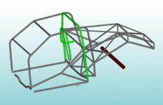
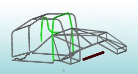
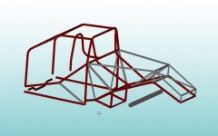
Since you're building off the shorter OEM frame to that much-taller 4 link bracket crossmember, isnt there going to be a risk of that section "folding" when under extreme stress at launch because it has to "neck down" to the OEM frame??
Are you planning on reinforcing that bracket x-member with gussetts and have tubing connecting to it up higher, maybe using the rollcage rear bars as the upper bracing?
What about the lower tubing? Since its not "level" with the bottom bars, do you have to add extra bracing there, too? I always thought the stresses had to be dealt with in a linear way?
I love your skills and the builds you guys are doing, so please dont take all this the wrong way. I'm just curious (and a bit concerned) b/c I dont know. Thanks.