97rada
New member
- Joined
- Feb 14, 2008
- Messages
- 5,410
It's gettin' there....
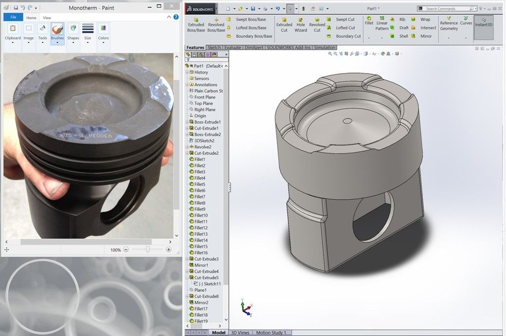
Impressive. I made some Pistons a few months back and all the detail is time consuming.

It's gettin' there....
The entire site should come with this disclaimer. For the the rednecks AND the Vendors to heed.Like I tried to explain to boy wonder earlier without being a complete prick....let's just assume I'm not just another dumb redneck wif a pick'em up truck.
I'm glad there are Swole's that exceed every known design parameter and keep lots of smart people employed trying to keep things un-Swoled.....lol
I think he called you a test mun-kee dave
Sent from my XT1053 using Tapatalk
I'm loading the last video now.
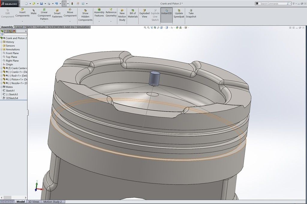
What I did was slow it down to 5 RPM's and zoomed in on that area of the nozzle and piston. I just put the nozzle and spray pattern in there as a static element.
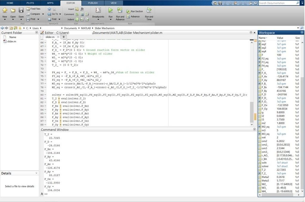
If I wanted to set this up for a really accurate analysis, I could take the known density of diesel, the total quantity injected, the orifice size, the number of orifices and the pressure being applied and calculate the velocity the fuel is actually leaving the nozzle. That combined with the relative piston speed would let you figure out just how much timing before and after TDC you can go without being outside the bowl.
Amazing work so far. It would be exceptional if you continued the analysis like you described.
Lol the singer was good from far but far from good.
")